
Knurling in Precision Machined Components: Types, Functions & Design Considerations
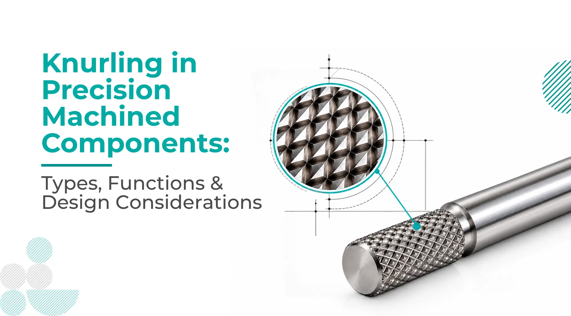


Knurling is a surface-forming operation used in precision machining to create controlled ridges or grooves on a component. Beyond improving grip, knurling can provide functional surface engagement for specific applications.
For precision machined components, knurling is a functional feature influenced by pattern, pitch, depth, component diameter, material and application. Proper tooling, workpiece support, alignment and process control are also essential for dimensional consistency and repeatable production.
This article covers knurling tools and methods, knurling patterns, material and design considerations, common defects, applications and manufacturing practices for producing consistent knurled components.
What Is Knurling?
Knurling is a machining operation used to create a controlled pattern of ridges or grooves on the surface of a component. In conventional form knurling, a patterned tool is pressed against the rotating workpiece, causing the material to deform and form the required knurled profile.
Unlike a conventional cutting operation, knurling primarily forms and displaces material to create the surface pattern. It is commonly performed on cylindrical components using tooling designed for the required knurling pattern.
Types of Knurling Tools for Precision Machined Components
The choice of knurling tool depends on the component, required pattern and production method. Different tooling arrangements control how the knurl is formed and how the tool interacts with the workpiece.
- Knurling Inserts: Knurling inserts are replaceable tooling elements used to produce a defined knurl profile. They are useful when different patterns or tooling configurations are required across production jobs, as the insert can be replaced without changing the complete tool holder. The selected insert should suit the required knurl pattern, pitch, component diameter and material. Tool wear also needs to be considered, particularly in repeat production where pattern consistency is important.
- Knurling Wheels: Knurling wheels have a patterned outer surface that forms the ridges on the rotating component. They are available for commonly used patterns such as straight, helical and diamond knurling, with different pitches available for different applications. Wheel selection is influenced by the workpiece diameter and material. The wheel also needs to engage the component correctly to produce a continuous pattern rather than defects such as double tracking or uneven knurling.
- Knurling Dies: Knurling dies form the required pattern through direct engagement with the component. They can be used where the tooling arrangement and component geometry allow controlled forming of the knurled surface. Since knurling generates forming forces, the tool alignment, component support and rigidity of the setup become important when using this type of tooling.
- Floating Knurling Tools: Floating knurling tools have a degree of movement that allows the tooling to accommodate the workpiece during the operation. This arrangement can be useful where controlled tool movement helps maintain contact with the component as the knurl develops. Their use depends largely on the machine setup, component geometry and required knurling operation, rather than being suitable for every type of part.
- Push-Type Knurling Tools: Push-type knurling tools form the pattern by applying pressure against the rotating workpiece. They can be used in machining setups where the component and tooling can withstand the forces generated during knurl formation. For this method, workpiece rigidity and secure holding are particularly important because excessive forming pressure can influence the component’s shape or pattern quality.
Form Knurling vs. Cut Knurling: Key Differences
Knurling can be produced using two basic approaches: form knurling and cut knurling. In form knurling, the tool presses against the workpiece and displaces material to create the required pattern. Cut knurling uses cutting edges to machine the grooves instead of primarily displacing the material.
Form knurling is widely used where the workpiece can withstand the forming pressure. Cut knurling can be considered when lower forming forces or tighter control over material displacement is required, depending on the material and component design.
How Does the Knurling Process Work?
The knurling process forms a defined pattern on a machined surface by bringing a patterned tool into contact with the rotating workpiece. The operation can be divided into four basic stages.
- Preparing the Machined Component: The component is first machined to its required base dimensions, with the knurled area clearly defined on the drawing. The surface should have enough material and support to withstand the forming operation without unwanted deformation.
- Selecting the Knurling Tool: The appropriate knurling wheel, insert or tool is selected based on the required pattern and pitch. The tooling must also suit the component diameter and the available space around the knurled section.
- Forming the Knurl: The tool is brought into contact with the rotating workpiece and pressure is applied to form the ridges. As the component rotates, the tool follows the surface and develops the selected pattern across the required length.
- Completing the Operation: Once the required knurled area has been formed, the tool is withdrawn and the component is checked for pattern definition, depth and dimensional consistency. Defects such as incomplete patterns, double tracking or uneven knurling can indicate issues with tooling or process setup.
Types of Knurling Patterns for Precision Components
The knurling pattern determines the geometry and direction of the ridges formed on the component surface. Pattern selection depends on how the knurled feature will be used, including requirements for grip, mechanical retention, torque resistance or engagement with a surrounding material.
The three commonly used patterns in precision-machined components are straight, helical and diamond knurling. Each produces a different surface profile and therefore offers different functional characteristics.
| Knurling Type | Pattern | Typical Functional Consideration |
|---|---|---|
| Straight knurling | Parallel ridges | Grip and selected retention applications |
| Helical knurling | Angled or spiral ridges | Directional engagement and specialised retention |
| Diamond knurling | Intersecting ridges | Multi-directional grip and mechanical engagement |
1. Straight Knurling
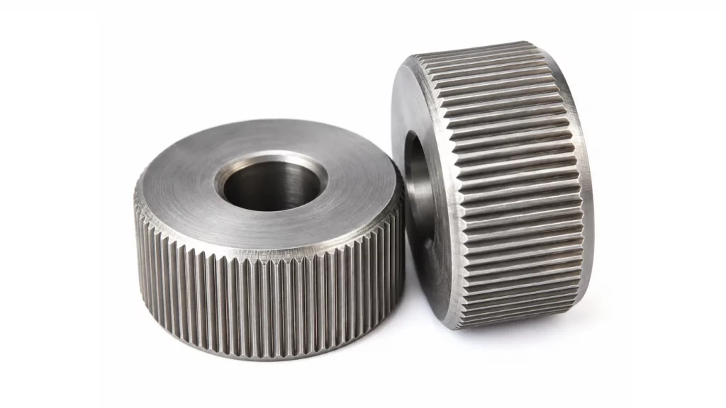
Straight knurling produces parallel ridges running along the surface of the component. The relatively simple pattern can provide a defined gripping surface while also creating mechanical engagement between the knurled component and another material.
Straight knurling is also used on selected moulding inserts, where the formed ridges provide an external profile for engagement with the surrounding plastic or rubber during moulding. The required pitch and depth should be selected according to the component dimensions and its intended function.
Benefits of Straight Knurling
- Provides a defined and consistent gripping surface
- Can improve mechanical retention in suitable applications
- Can be used on moulding inserts for engagement with moulded materials
- Offers a straightforward pattern for applications requiring parallel ridges
When to Choose Straight Knurling
- When the application requires a parallel-ridge pattern
- For grip-related applications
- For selected mechanical retention requirements
- When the component geometry and material are suitable for the pattern
2. Helical Knurling
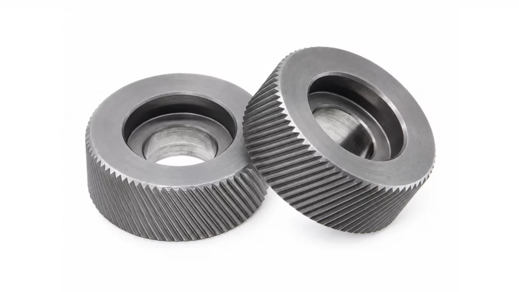
Helical knurling creates angled or spiral ridges around the component rather than running directly along its length. The direction of these ridges changes how the knurled surface engages with a mating or surrounding material.
The helical pattern can therefore be useful where the direction of mechanical engagement is an important part of the component design. Selection should consider the helix direction, component geometry and loading conditions rather than treating the pattern as a surface-finish choice alone.
Benefits of Helical Knurling
- Creates an angled form of surface engagement
- Can support specialised retention requirements
- Provides a defined directional pattern
- Can be considered where straight knurling is not suitable for the required function
When to Choose Helical Knurling
- When an angled or spiral pattern is required
- For applications involving directional mechanical engagement
- When the retention design benefits from a helical profile
- When the component geometry and expected loads support the pattern
3. Diamond Knurling
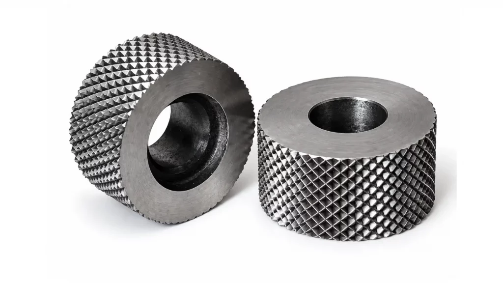
Diamond knurling is produced by two sets of angled ridges that intersect to form a diamond-shaped pattern. The intersecting ridges create a textured surface with engagement in multiple directions.
This pattern is commonly considered where the component requires a stronger textured interface for grip or mechanical engagement. The diamond profile should still be selected according to the component’s material, dimensions and functional requirements rather than appearance alone.
Benefits of Diamond Knurling
- Provides multi-directional surface engagement
- Creates a defined textured profile for improved grip
- Can support mechanical retention in suitable applications
- Produces an intersecting pattern across the knurled area
When to Choose Diamond Knurling
- When multi-directional grip is required
- For selected mechanical engagement applications
- When the component requires an intersecting ridge pattern
- When the material, diameter and expected loading are suitable for diamond knurling
Material Considerations for Knurling
The material of the machined component has a direct influence on how the knurling pattern forms and how consistently it can be reproduced. Materials with different levels of hardness, strength and ductility will respond differently to the forces applied during knurling.
Key material considerations include:
- Hardness: Harder materials may require greater forming force and appropriate tooling.
- Ductility: Materials that can deform without cracking are generally more suitable for forming-based knurling.
- Strength: Higher-strength materials can increase tool loading and influence pattern formation.
- Surface condition: The starting surface should be suitable for producing a consistent knurled profile.
- Material stability: The component should maintain the required dimensions and mechanical properties after processing.
Brass, aluminium, steel and stainless steel can all be used for knurled components, but the process parameters and tooling should be selected according to the specific material grade and component design. Material selection should also consider the final function of the knurled surface, particularly where it is intended for mechanical retention or interaction with a moulded material.
What Functions Can Knurling Provide in Precision Components?
Knurling can serve more than a surface-texturing purpose in precision machined components. Depending on the pattern, dimensions and application, a knurled surface can improve handling, create mechanical engagement and support the functional performance of an assembled component.
1. Improving Grip and Manual Handling
Knurling creates raised ridges that increase surface texture and provide better contact between the component and the operator’s fingers or a mating tool. This makes it useful for knobs, adjustment components, handles and other parts that require controlled manual operation. The required pattern and knurl depth should be selected according to the desired grip and the size of the component.
2. Increasing Mechanical Retention
A knurled surface can improve mechanical retention by creating an irregular profile that engages with a surrounding material or mating component. This is particularly useful for moulding inserts and embedded metal components, where the knurled area helps resist movement after the component is moulded into plastic or another material. The effectiveness of the retention depends on factors such as knurl pattern, depth, pitch, material combination and the direction of the applied load.
3. Supporting Torque Transfer
Knurling can help resist relative rotation between two components by increasing mechanical engagement at the interface. This makes knurled surfaces useful where a component needs to transmit or withstand rotational loads without relying solely on a smooth interference surface. For torque-transfer applications, the knurl geometry and engagement area should be selected according to the expected loading conditions.
4. Supporting Press-Fit or Interference Assemblies
A knurled surface can be incorporated into selected press-fit or interference-fit designs to increase surface engagement between the component and its mating material. The displaced material and ridged profile can contribute to retention when the component is assembled into a compatible bore or surrounding material. However, knurling should not be treated as a substitute for proper interference-fit design. Diameter, material properties, knurl depth and assembly force must be considered together.
5. Providing Controlled Surface Texture
Knurling can also be specified where a controlled surface texture is required for functional or handling purposes. Unlike an incidental rough surface, a defined knurl pattern provides a repeatable geometry that can be incorporated into the component design.
Where Is Knurling Used?
Knurling is used in precision-machined components where a textured or mechanically engaging surface provides a specific functional advantage. Its application depends on the required interaction between the component and the user, mating component or surrounding material.
Common applications include:
- Knobs and handles: To provide improved manual grip.
- Adjustment components: To make controlled manual adjustment easier.
- Moulding inserts: To provide mechanical engagement with surrounding plastic or rubber.
- Embedded metal components: Where the external profile helps resist movement within a moulded assembly.
- Torque-transfer components: Where the knurled interface contributes to resistance against relative rotation.
- Selected press-fit components: Where the knurled surface forms part of the mechanical engagement.
The appropriate knurl pattern and dimensions depend on the application. A pattern selected for manual grip, for example, may not be appropriate for an insert designed to withstand rotational or axial loads within a moulded component.
Design Considerations for Knurling Precision Components
These are general guidelines. Confirm them against your tooling supplier’s recommendations and the application.
| Design factor | Guideline | Reason |
|---|---|---|
| Part diameter | Generally, ≥ 6 mm | Smaller diameters deflect or deform under tool pressure |
| Distance from shoulders | Typically, ≥ 1 mm clearance | Prevents tool interference and incomplete patterns |
| Starting diameter | Undersized to allow for displacement | Form knurling raises the OD |
| Pitch and diameter | Select a suitable pitch for the component diameter | Helps maintain proper pattern tracking and reduce double tracking |
| Adjacent features | Keep clear of threads and sealing surfaces | Prevents distortion from displaced material |
Knurl pitch should be selected according to the component diameter, material, tooling and intended function. As a general guideline, smaller components may require finer pitches, while larger gripping surfaces can accommodate coarser patterns. For example, components around Ø6–10 mm may use pitches in the 0.8–1.2 mm range, while Ø10–25 mm components may suit approximately 1.2–1.8 mm pitches. During form knurling, material displacement can also increase the finished diameter, so the pre-knurl diameter may be estimated as approximately Target OD − (0.4 to 0.6 × pitch). These values are only starting guidelines; the final pitch and starting diameter should be confirmed against the selected tooling, material and component geometry.
Knurling Cost: Factors That Affect Component Pricing
The cost of knurling depends on tooling, setup time, component geometry, production volume, machining time and inspection requirements. For low-volume production, setup and tooling costs have a greater effect on the cost per component. In higher-volume production, these costs are distributed across a larger run, while consistent machining conditions improve cycle efficiency and reduce variation.
Component design also influences cost. A simple knurled section that can be produced within the existing machining setup may require less processing than a component with multiple knurled areas, restricted tool access or tighter dimensional requirements.
As a general benchmark, knurling may add approximately 10–25% to component cost for runs below 100 pieces, while optimized tooling and repeatable conditions may reduce the incremental impact to around 3–8% at volumes above 1,000 pieces. Actual cost varies significantly with component geometry, material, knurling pattern, tooling, setup time, cycle time and inspection requirements, so these figures should be treated as indicative rather than fixed pricing.
Tips for Achieving a Consistent & High-Quality Knurled Finish
Producing a consistent knurled finish requires attention to the component, tooling and machining conditions throughout the process. The following practices can help improve pattern consistency and reduce common knurling problems:
- Select the knurl pattern according to function: Choose straight, helical or diamond knurling based on the required grip, retention or mechanical engagement rather than appearance alone.
- Match the tooling to the component: Tool type, pitch and geometry should be compatible with the workpiece diameter, material and required knurl profile.
- Maintain accurate tool alignment: Correct alignment helps prevent tracking problems and inconsistent pattern formation.
- Provide adequate workpiece support: Long, thin or hollow components may require additional support to prevent deflection during the operation.
- Control tool condition: Worn tooling can affect pattern definition, depth and repeatability, particularly during high-volume production.
- Consider material behaviour: Process conditions should be appropriate for the hardness, strength and ductility of the workpiece material.
- Protect adjacent precision features: The knurling operation should be planned so that forming forces and material displacement do not compromise nearby threads, shoulders or critical dimensions.
- Inspect the finished knurl: Visual appearance should be checked along with relevant dimensional and functional requirements to ensure the knurled feature performs as intended.
Common Knurling Defects and Their Causes
Knurling defects can affect the appearance, dimensions and functional performance of the finished component. Common problems are often related to tooling, alignment, material behaviour, workpiece support or unsuitable process conditions.
| Defect | Possible Cause |
|---|---|
| Incomplete pattern | Insufficient tool engagement or unsuitable process conditions |
| Double tracking | Incorrect tool alignment or unsuitable pitch-to-diameter relationship |
| Uneven knurl depth | Inconsistent tool engagement or inadequate workpiece support |
| Material tearing | Excessive forming force or unsuitable material/process conditions |
| Component distortion | Excessive forming pressure or insufficient part rigidity |
| Worn or weak pattern | Tool wear or incorrect tooling |
| Burrs or sharp edges | Tool condition, setup or finishing issues |
| Inconsistent pattern between batches | Variation in tooling, setup or process control |
Drunken knurling, often referred to as double tracking, occurs when the knurl pattern fails to track correctly around the circumference of the workpiece. It can result from an unsuitable relationship between the component diameter and knurl pitch, incorrect tool alignment or unsuitable process conditions. Proper tooling selection and machine setup are therefore important for maintaining consistent pattern formation.
Knurled Component Manufacturing at Schilthorn Precision
With 15+ years of engineering and manufacturing experience, Schilthorn Precision manufactures precision machined components with application-specific knurled features. Our capabilities include CNC machining, knurled inserts and brass component manufacturing, with a focus on dimensional consistency and repeatable production.
Knurling can be produced in straight, helical and diamond patterns, depending on the functional requirements of the component. From material selection and tool setup to machining and inspection, the process is controlled to achieve consistent knurl quality for OEM applications.
Looking for precision knurled components? Contact Schilthorn Precision to discuss your requirements.
FAQ’s
1. Does knurling change the diameter of a machined component?
Yes. Knurling displaces material and can affect the effective outside diameter of the component. The starting diameter and knurling parameters should therefore be considered during component design.
2. How do you specify knurling on an engineering drawing?
The drawing should clearly specify the knurl type, pitch, depth and location. A complete representation of the knurl pattern in the CAD model is not always necessary.
3. Can knurling be performed on thin-walled or hollow components?
Yes, depending on the component geometry and material. Thin-walled or hollow components may require suitable workholding and process control to prevent deformation during knurling.
4. Can knurling be applied to hardened or heat-treated materials?
It depends on the material hardness and the selected knurling process. Harder materials may require appropriate tooling and controlled forming conditions.
5. What causes double tracking during knurling?
Double tracking can occur due to incorrect tool alignment, unsuitable tooling or poor synchronisation between the tool and rotating workpiece. Proper setup and process control help prevent this defect.
6. Does knurling affect the dimensional tolerance of a precision component?
Yes. Since knurling forms and displaces material, it can influence the dimensions around the knurled area. The knurl should therefore be considered when defining the component’s dimensional requirements.
7. How does material selection affect the knurling process?
Material hardness, strength and ductility influence how the component responds to the forming forces. The knurling tool and process parameters should be selected according to the material and component design.
8. Can knurling be used on moulding inserts for better retention?
Yes. Knurled surfaces can provide mechanical engagement between a metal insert and the surrounding moulded material, helping improve retention in suitable moulding applications.
9. Can Knurling Be Done on Non-Cylindrical Parts?
Knurling is primarily suited to cylindrical or rotationally symmetrical components because the workpiece rotates while the tool forms the pattern. Non-cylindrical components may require specialised tooling or machining arrangements and are generally less straightforward than conventional cylindrical knurling.