
Surface Finish Standards in Precision Machining: Ra Values Explained
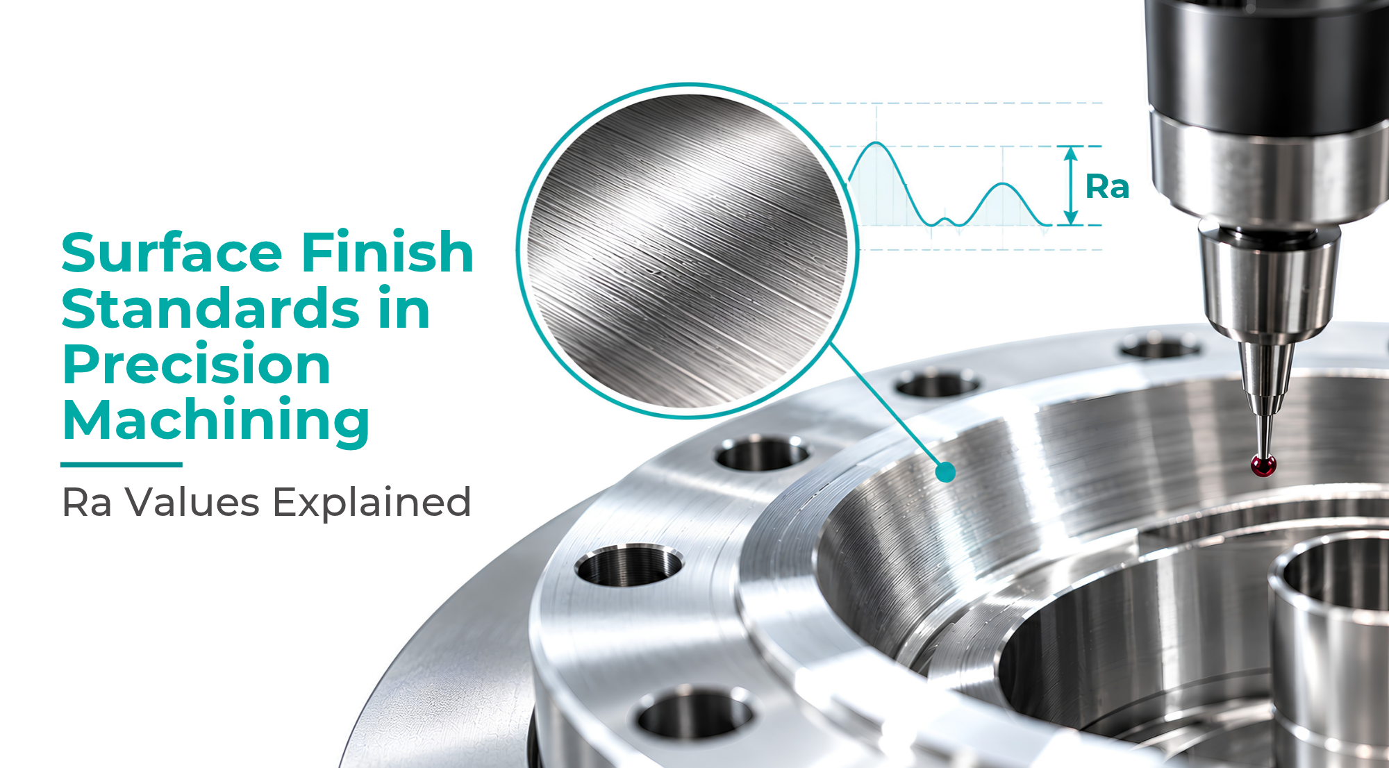


In precision machining, dimensional accuracy is only one part of component quality. The condition of the machined surface also affects how a component fits, moves, seals, wears and performs in its intended application. A component may meet its dimensional tolerances but still require further finishing if its surface texture does not meet the engineering drawing requirements.
One of the most commonly used parameters for specifying surface roughness is Ra (arithmetical mean deviation of the assessed profile). It provides a numerical measure of the deviations in a measured surface profile from its mean line. In manufacturing drawings, Ra values are generally expressed in micrometres (µm) and help communicate the required surface texture between design, machining and quality inspection teams.
However, selecting a surface finish is not simply a matter of choosing the lowest possible Ra value. The appropriate requirement depends on the component’s function, material, manufacturing process and applicable specifications. Understanding surface finish standards and how Ra values are measured helps manufacturers interpret drawings correctly, select suitable machining parameters and verify that finished components meet the required criteria.
This guide explains Ra values, relevant surface finish standards, measurement methods and the factors that influence surface roughness in precision machining.
What Is Surface Finish in Precision Machining?
Surface finish describes the texture of a component’s surface after manufacturing. It includes characteristics such as roughness, waviness and surface irregularities that develop during machining or other production processes. In technical specifications, these characteristics are assessed using defined parameters rather than visual appearance alone. Surface roughness is particularly important in precision-machined components because it can influence contact between mating parts, friction, wear, sealing performance and the effectiveness of certain coatings or finishing treatments.
For example, a shaft that fits into a bearing, a sealing face and a mounting surface may each require a different surface texture. The appropriate finish depends on how the surface functions in the assembly, not simply on how smooth it looks. Surface finish requirements are therefore specified on engineering drawings or in technical documentation. Parameters such as Ra help turn these requirements into measurable acceptance criteria for manufacturing and inspection.
What Does Ra Mean in Surface Roughness?
Ra stands for arithmetical mean deviation of the assessed profile. It measures the average of the absolute deviations of a measured surface profile from its mean line over a defined evaluation length. In simple terms, it indicates how much the measured profile varies from its average line. Ra is widely used in precision machining because it provides a consistent numerical way to specify and assess surface roughness. Instead of relying on descriptions such as “smooth” or “rough,” manufacturers can work with a defined value on an engineering drawing and verify the result through appropriate measurement.
For example, a surface specified as Ra 0.8 µm has a lower average profile deviation than one specified as Ra 3.2 µm. This generally indicates a smoother surface in terms of the Ra parameter, although Ra alone does not describe every feature of the surface texture. It is also important to distinguish Ra from other roughness parameters. Two surfaces can have the same Ra value but differ in peak height, valley depth, or the distribution of surface irregularities. Where these characteristics affect component performance, additional parameters may be needed.
How to Read an Ra Surface Finish Chart
An Ra surface finish chart helps engineers, machinists and quality inspectors compare surface roughness values specified on engineering drawings. Ra is expressed in micrometres (µm) and a lower value generally indicates a smoother measured profile.
The table below provides an indicative guide to commonly encountered Ra values and their general interpretation in precision machining. These descriptions are not universal specifications or guaranteed results for a particular manufacturing process. Actual surface finish depends on factors such as material, tool condition, machining parameters, component geometry and any secondary finishing operations.
| Ra value (µm) | General surface description | Typical manufacturing context |
|---|---|---|
| 6.3 | Relatively rough | May be suitable for general surfaces where a finer finish is not functionally required |
| 3.2 | Standard machined finish | Common reference value for general-purpose machined surfaces |
| 1.6 | Finer machined finish | Used where the component requires a smoother surface than a general machined finish |
| 0.8 | Smooth finish | May be specified for components with more demanding surface-texture requirements |
| 0.4 | Very smooth finish | May require carefully controlled machining or an additional finishing operation |
| 0.2 and below | Very fine finish | Typically associated with specialised finishing requirements and suitable processes |
Note: The table is intended for general guidance. It does not prescribe the correct Ra value for a specific component or guarantee that a particular machining process will achieve it.
How should you interpret these values?
The difference between Ra 3.2 µm and Ra 0.8 µm is not simply a matter of appearance. A lower specified value may require different cutting conditions, tooling, additional finishing operations and more careful inspection. However, a lower Ra value is not automatically better for every component. The correct value is the one that meets the functional requirements and engineering specification without adding unnecessary manufacturing cost.
When interpreting a drawing, check the specified Ra value, the surface to which it applies and any additional surface-texture requirements. These details help the machining and inspection teams determine whether the component meets the intended acceptance criteria.
Which Surface Finish Standards Apply to Precision Machining?
Surface finish requirements need to be specified and assessed using recognised standards so that design, manufacturing and inspection teams interpret the requirements consistently. These standards define how surface texture is indicated, measured and evaluated rather than relying on subjective descriptions such as smooth or rough. For precision machining, the applicable standard depends on the drawing, customer requirements and the surface-texture parameters being specified.
ISO 21920: Surface Texture by Profile
The ISO 21920 series cover profile-based surface-texture specification and assessment. It addresses how surface texture is indicated on technical product documentation and how profile parameters are assessed.
This series is particularly relevant when interpreting modern engineering drawings that specify Ra or other profile parameters. It helps establish a consistent basis for communicating surface-texture requirements and evaluating measured results.
ISO 1302: Indication of Surface Texture
ISO 1302 is widely referenced in older engineering drawings and documentation for the indication of surface texture in technical product documentation. However, it has been superseded by newer standards in the ISO 21920 series for profile-based surface-texture specification.
When working with existing drawings, manufacturers should follow the standard and edition specified by the customer or governing documentation rather than assuming that every drawing uses the latest convention.
Why Do These Standards Matter in Manufacturing?
Applying the correct surface-texture standard helps avoid misunderstandings between design and production teams. A specified Ra value alone may not communicate every detail needed for measurement and acceptance. Depending on the requirement, the applicable standard may also define assessment conditions, filtering, evaluation length and other parameters.
Before machining begins, manufacturers should review the drawing notes, surface-texture symbols, specified parameters and applicable standard. This makes it easier to select a suitable process and assess the finished component against the intended requirements.
Key takeaway: Always interpret an Ra requirement in the context of the applicable drawing and standard. The numerical value is important, but the measurement and acceptance conditions matter too.
How Is Surface Roughness Measured?
Surface roughness is measured using specialised instruments that capture variations in a surface profile and calculate parameters such as Ra. In precision machining, measurement helps determine whether a finished component meets the surface-texture requirements specified in its engineering drawing.
The measurement method depends on the component’s geometry, material, required accuracy and applicable inspection procedure.
1. Contact Profilometer
A contact profilometer uses a fine stylus that moves across the component’s surface. The instrument records profile variations and calculates roughness parameters such as Ra.
Contact profilometers are widely used for inspecting machined metal surfaces because they provide quantitative measurements. However, the stylus tip, measurement direction, instrument settings and surface geometry can influence the result.
2. Optical Surface Measurement
Optical measurement systems use light-based techniques to assess surface topography without requiring a stylus to contact the component. Depending on the technology, they can provide two-dimensional profiles or three-dimensional surface information.
These systems can be useful for delicate surfaces, complex geometries, or applications where contact measurement is unsuitable. Their suitability depends on the surface material, reflectivity, geometry and measurement requirements.
3. Factors That Affect Measurement Results
Using an appropriate instrument is only part of the process. To obtain meaningful and repeatable results, inspection teams should consider:
- Measurement direction: The stylus or measurement path should follow the direction required by the inspection procedure, as roughness can vary with machining marks.
- Filtering and evaluation length: These settings influence which surface variations contribute to the reported roughness value.
- Surface condition: Dirt, oil, burrs and handling damage can affect measurements.
- Instrument calibration and setup: The equipment must be suitable for the required measurement range and maintained according to its calibration requirements.
Why Does Measurement Matter?
A visual inspection may identify scratches, tool marks, or obvious surface defects, but it cannot reliably establish a numerical Ra value. Instrument-based measurement provides quantitative evidence that the specified surface-texture requirement has been assessed. For precision-machined components, the inspection method should therefore be selected according to the drawing, applicable standard and functional requirements of the surface.
What Factors Affect Ra Values in CNC Machining?
Achieving the required surface finish in CNC machining depends on more than the machine’s accuracy. Cutting parameters, tool condition, workpiece material, machine stability and the finishing method all influence the surface texture produced. Understanding these factors helps manufacturers select suitable machining conditions and avoid unnecessary finishing operations.
1. Cutting Speed, Feed Rate and Depth of Cut
Cutting parameters directly influence how the cutting tool interacts with the workpiece.
- Feed rate: A higher feed per revolution or tooth can produce more pronounced tool marks, depending on the tool geometry and machining operation.
- Cutting speed: An appropriate cutting speed helps maintain stable cutting conditions and can reduce certain surface defects. The ideal value depends on the material and tooling.
- Depth of cut: Excessive or unsuitable cutting conditions can contribute to vibration, tool deflection, or unstable machining, affecting the resulting surface.
These parameters should be selected together rather than adjusted independently to achieve a target Ra value.
2. Cutting Tool Geometry and Condition
Tool geometry, edge sharpness, coating and wear affect the finish left on the component. A worn or damaged cutting edge can produce roughness, scratches and irregular tool marks. Selecting suitable tooling for the workpiece material and replacing or reconditioning tools, when necessary, helps maintain consistent surface quality across production batches.
3. Workpiece Material
Different materials respond differently to machining. Their hardness, ductility, microstructure and tendency to form built-up edges can influence the resulting surface. For example, a material that tends to adhere to the cutting edge may develop surface imperfections under unsuitable cutting conditions. Machining parameters and tool selection must therefore be matched to the specific material rather than applied uniformly across all components.
4. Machine Stability and Vibration
Machine rigidity, workpiece clamping, tool overhang and vibration can all affect surface roughness. Chatter may leave visible patterns or periodic marks on a machined surface, making it difficult to achieve a consistent finish. Secure workholding, appropriate tool setup and stable cutting conditions help minimise these problems.
5. Finishing Operations
Some components require additional operations after the main machining process to achieve their specified surface texture. Depending on the material, geometry and functional requirements, these may include grinding, honing, lapping, or polishing. Each process produces different surface characteristics and has its own limitations. Additional finishing should be selected according to the drawing requirements. It is not automatically necessary simply because a component is precision-machined.
The practical takeaway: Consistent Ra values come from controlling the machining process as a whole. The objective is to achieve the specified surface texture repeatably while balancing component performance, inspection requirements and manufacturing cost.
How Do You Choose the Right Surface Finish for a Machined Component?
The right surface finish is determined by how a component needs to function, not simply by how smooth its surface can be made. Specifying an unnecessarily fine finish may increase machining time and inspection costs, while an unsuitable finish can affect fit, sealing, wear or component performance. Manufacturers should evaluate the functional requirements of each surface before selecting an Ra value.
1. Consider the Component’s Function
Different surfaces serve different purposes, so they may require different roughness limits.
- Mating surfaces: The finish can influence how accurately two components fit together and make contact.
- Sealing surfaces: Surface texture can affect sealing performance, depending on the seal design, material and operating conditions.
- Sliding or rotating surfaces: Roughness can influence friction, lubrication and wear.
- General mounting surfaces: These may not require the same finish as precision interfaces, provided they meet the specified dimensional and functional requirements.
These are general considerations, not fixed Ra recommendations. The required value should come from the component design, engineering drawing, or applicable specification.
2. Check the Engineering Drawing
Before machining begins, review the drawing for the specified Ra value, surface-texture symbols, dimensional tolerances and any additional requirements. Also confirm whether the finish applies to a particular face, bore, shaft, or the entire component. Different surfaces on the same part may have different acceptance criteria. Clarifying these requirements early helps prevent avoidable rework and disagreements during final inspection.
3. Match the Finish to the Manufacturing Process
The selected machining process should be capable of achieving the required surface texture consistently. Depending on the component geometry, material and finish requirement, the process may involve turning, milling, grinding, honing, or another finishing operation. A process that achieves the target Ra on one material or geometry may not deliver the same result on another. Manufacturers should consider both the achievable finish and the repeatability of the process across production batches.
4. Balance Surface Quality with Manufacturing Cost
A finer surface finish may require slower cutting conditions, additional machining passes, specialised tooling, or secondary finishing. These requirements can increase production time and inspection effort. The objective is therefore to achieve the specified surface finish without overprocessing the component. Where the application does not require an exceptionally fine finish, a suitable standard machining process may be sufficient.
Ultimately, selecting the right Ra value requires coordination between design, machining and quality teams. Clear specifications and process planning help ensure that surface quality meets functional needs without adding unnecessary manufacturing complexity.
How Schilthorn Precision Helps Achieve the Required Surface Finish
Achieving the specified surface finish requires a machining process suited to the component’s material, geometry and engineering requirements. Schilthorn Precision offers CNC milling, CNC turning and precision grinding to support the manufacture of components with defined dimensional and surface-finish requirements.
Schilthorn’s published CNC milling capabilities include tolerances up to ±10 microns and a listed surface finish of Ra 1.5–3 µm. The achievable result for an individual component depends on its geometry, material, machining conditions and specified requirements.
For components requiring additional finishing, Schilthorn also offers grinding and surface-treatment services. Reviewing the component drawing and functional requirements helps determine which manufacturing processes are appropriate for the application.
If your project requires precision-machined components with specified surface-finish requirements, contact Schilthorn Precision to discuss your drawings and manufacturing needs.
FAQs
1. What is a good Ra value for precision machining?
There is no single Ra value that is suitable for every precision-machined component. The required value depends on the component’s function, material, mating conditions and engineering specifications. Commonly encountered values include Ra 3.2 µm, 1.6 µm, 0.8 µm and 0.4 µm, but the drawing determines the actual requirement.
2. What is the difference between Ra and Rz?
Ra represents the arithmetic mean of the absolute profile deviations from the mean line over the assessment length. Rz is a different roughness parameter based on profile peak and valley characteristics, as defined by the applicable measurement standard. The two parameters describe different aspects of surface texture and should not be treated as interchangeable.
3. Does a lower Ra value always mean better quality?
No. A lower Ra value indicates lower average profile deviation, but it does not automatically mean that a component will perform better. The appropriate surface finish depends on functional requirements such as sealing, friction, wear and fit. An unnecessarily fine finish may increase manufacturing cost without improving component performance.
4. How is Ra measured on a machined component?
Ra is commonly measured using a contact profilometer with a stylus that traces the surface profile. Optical measurement systems may also be suitable for certain applications. The instrument, measurement direction, filtering and evaluation conditions should follow the applicable specification and inspection procedure.
5. Which ISO standard covers surface roughness?
The ISO 21920 series address profile-based surface-texture specification and assessment. Older drawings may reference ISO 1302 for surface-texture indications. Manufacturers should follow the standard and edition specified in the engineering documentation and confirm the applicable requirements before inspection.