What is Thermal Expansion? A Precision Engineer’s Guide to Managing Heat


What Is Thermal Expansion?
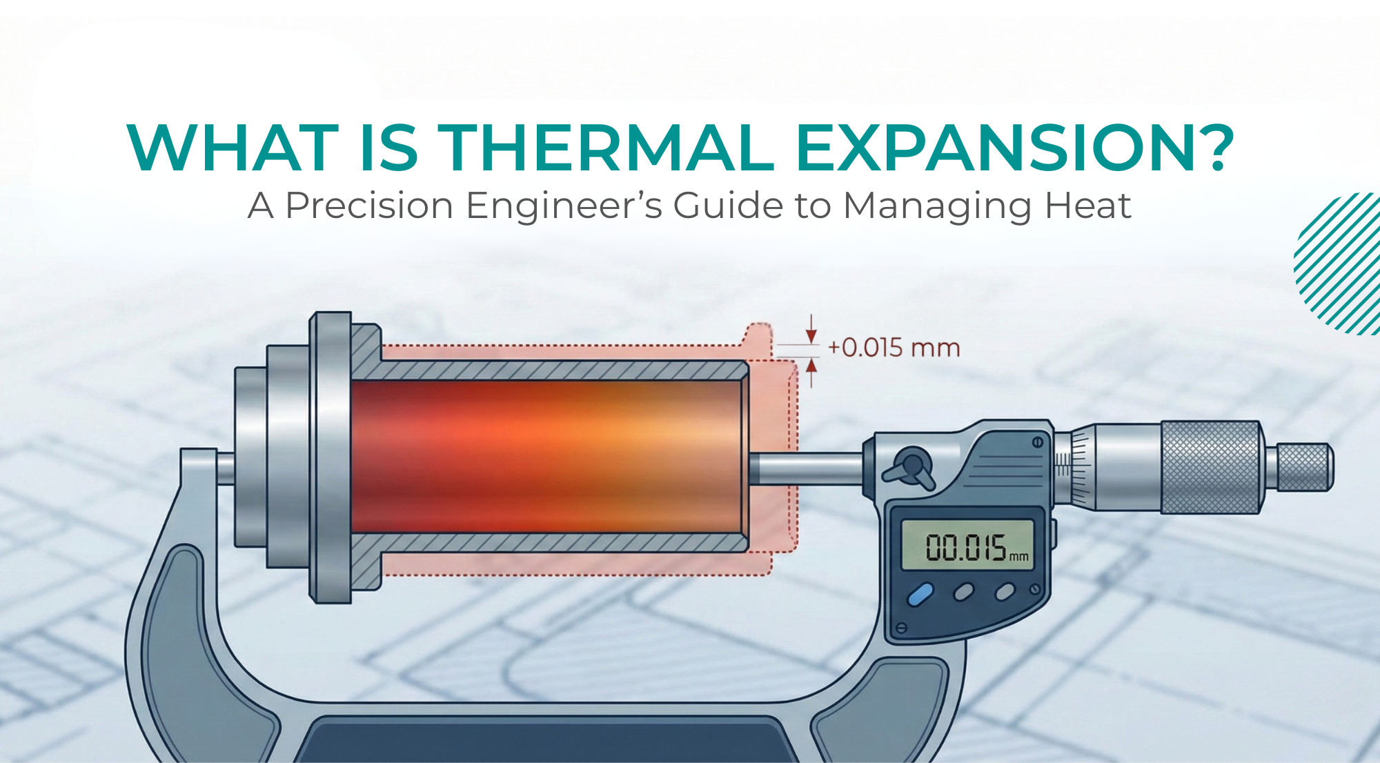
Thermal expansion is the dimensional change that occurs in a material when its temperature varies. It is a fundamental thermophysical property of solid engineering materials and arises from atomic-level interactions within the material structure.
As temperature rises, atomic vibration amplitude increases, because interatomic bonding forces are inherently asymmetric, the average spacing between atoms expands with thermal energy. This change in mean interatomic distance produces measurable dimensional growth at the macroscopic scale.
Thermal expansion is not a material defect or instability. It is an inherent and predictable material characteristic that can be mathematically modelled. The extent of expansion depends on:
- Material composition
- Bonding structure
- Crystal lattice arrangement
- Temperature range
- Phase stability
In engineering systems, thermal expansion influences structural alignment, stress development, tolerance accumulation and assembly compatibility. Its behaviour is governed by the material’s coefficient of thermal expansion (CTE), which defines the proportional relationship between temperature change and dimensional response.
Understanding what thermal expansion is in precision engineering requires examination of its physical mechanism, mathematical representation and material dependence across structural metals and engineering alloys.
What Is the Coefficient of Thermal Expansion (CTE)?
The coefficient of thermal expansion (CTE) is a fundamental thermophysical property that quantifies how much a material changes dimension in response to temperature variation. It defines the proportional relationship between temperature change and resulting dimensional strain in a solid material.
For solids undergoing uniform heating within standard engineering temperature ranges, dimensional growth is approximately linear with temperature. This proportional behaviour is represented through the linear coefficient of thermal expansion. The linear approximation remains valid within moderate temperature limits, before material behaviour approaches phase transformation, microstructural change or high-temperature nonlinearity.
The linear expansion relationship is expressed as:
ΔL=α⋅L⋅ΔT
Where:
- ΔL = change in length.
- α = linear coefficient of thermal expansion.
- L = original length.
- ΔT = temperature change.
The coefficient α represents the fractional increase in length per unit length for each degree of temperature rise. It is typically expressed in:
- µm/m·°C
- ×10⁻⁶ /°C
For example, if a material has a CTE of 12 µm/m·°C, it will expand by 12 micrometres for every metre of length for each 1°C increase in temperature.
Physical Meaning of CTE:
CTE does not describe total expansion directly. It describes sensitivity to temperature. Materials with higher CTE values respond more strongly to temperature variation, while materials with lower CTE values exhibit greater dimensional stability.
The magnitude of CTE is influenced by:
- Interatomic bonding strength.
- Crystal lattice structure.
- Alloy composition.
- Phase behaviour.
Materials with stronger atomic bonding generally exhibit lower expansion rates because atomic spacing changes less with increasing thermal energy.
Worked Calculation Example
Consider a 500 mm long steel bar with a linear CTE of 12 µm/m·°C.
If the temperature increases by 30°C:
ΔL=12×0.5×30
ΔL=180 µm
The bar will increase in length by 0.18 mm.
While this dimensional change may appear small, it becomes significant in systems requiring tight geometric control or dimensional compatibility between multiple components.
Types of Thermal Expansion
Thermal expansion in solid materials is classified based on how dimensional change occurs relative to geometry and temperature distribution. This classification allows engineers to distinguish between uniform dimensional growth and thermally induced geometric distortion.
Linear Expansion
Linear expansion is a dimensional change along a single axis when a material experiences uniform temperature variation. Every linear dimension length, diameter, thickness or spacing increases proportionally to the temperature change.
For example, if a 1-metre-long steel bar is uniformly heated, its total length increases while its geometric form remains unchanged. The expansion occurs equally along the entire axis.
Linear expansion directly affects:
- Overall length.
- Shaft diameters.
- Bore sizes.
- Plate thickness.
- Feature spacing.
Because engineering tolerances are typically defined in linear units, linear expansion forms the basis of most dimensional calculations.
Volumetric Expansion
Volumetric expansion refers to the overall change in volume of a material due to temperature rise. In isotropic solids subjected to uniform heating, expansion occurs simultaneously in all three spatial directions.
As each linear dimension increases, the total volume increases accordingly. While the shape of the component may remain geometrically similar, its mass distribution and internal stress state may change slightly depending on constraints.
Volumetric expansion becomes particularly relevant in:
- Large structural blocks.
- Cast components.
- Pressure-containing vessels.
- Thick-section parts.
Differential Expansion
Differential expansion occurs when temperature distribution is not uniform or when materials with different thermal expansion characteristics are joined together.
Unlike uniform linear expansion, differential expansion produces uneven strain within a component or assembly. This can result in:
- Warping
- Bending
- Internal stress
- Geometric distortion
If one side of a metal plate experiences higher temperature than the opposite side, the hotter region expands more, causing curvature. Similarly, when two bonded materials with different coefficients of thermal expansion are heated, each attempt to expand by a different amount. Because they are constrained, internal stresses develop at the interface.
Differential expansion is often more structurally significant than uniform expansion because it affects geometric relationships rather than simply increasing size.
Thermal Expansion Coefficients of Common Engineering Materials
The linear coefficient of thermal expansion (CTE) varies significantly across materials. The following values represent approximate average linear CTE values near room temperature (~20°C). Actual values vary with temperature range, heat treatment condition and alloy composition.
Approximate CTE Values (µm/m·°C at ~20°C)
| Material | Linear CTE (µm/m·°C) | Material Category |
|---|---|---|
| Fused Quartz | 0.5 | Ultra-Low Expansion |
| Invar (Fe–36Ni) | 1.2 | Low Expansion Alloy |
| Tungsten Carbide | 4.5 | Hard Composite |
| Titanium (Ti-6Al-4V) | 8.6 | Aerospace Alloy |
| H13 Tool Steel | 10.4 | Tool Steel |
| Carbon Steel (1020) | 11.7 | Structural Steel |
| 304 Stainless Steel | 16.0 | Austenitic Stainless |
| 303 Stainless Steel | 17.3 | Austenitic Stainless |
| 17-4 PH Stainless Steel | 10.8 | Precipitation-Hardened |
| Inconel 718 | 13.0 | Nickel Alloy |
| 6061 Aluminium | 23.6 | Aluminium Alloy |
| 7075 Aluminium | 23.6 | Aluminium Alloy |
| Magnesium | 26.0 | Light Metal |
| PEEK (Virgin) | 50.0 | Engineering Polymer |
| PTFE (Virgin) | 120–140 | Fluoropolymer |
| Nylon | 90.0 | Engineering Polymer |
Interpretation of Material Differences
Several important engineering observations can be made:
- Aluminium expands approximately twice as much as carbon steel for the same temperature change.
- Austenitic stainless steels exhibit higher expansion than carbon steels due to their crystal structure.
- Titanium alloys demonstrate comparatively lower expansion among structural metals.
- Invar is engineered specifically for dimensional stability in precision instrumentation.
- Engineering polymers expand six to nine times more than common metals.
The difference between 12 µm/m·°C and 23 µm/m·°C becomes significant over long component lengths or moderate temperature variation. For a 1 metre component exposed to a 40°C change:
- Carbon steel expands ≈ 480 µm
- Aluminium expands ≈ 944 µm
- PTFE expands several millimetres
This variation directly influences assembly design, stress development and dimensional compatibility.
Major Causes of Thermal Expansion in Machining
Thermal expansion occurs when heat introduced into the machining system causes dimensional change in the workpiece, tooling or machine structure. In high-precision applications, where tolerances are often below a few microns, even small temperature variations can lead to measurable dimensional drift. Thermal expansion is driven by multiple heat sources acting simultaneously throughout the machining cycle.
- Cutting Action and Friction:
The interaction between the cutting tool and the workpiece generates heat due to material deformation and friction. High cutting speeds and materials with poor thermal conductivity, such as titanium and nickel-based alloys, create localised hot zones that cause temporary workpiece expansion. During high-speed turning of a titanium shaft, the outer surface temperature may rise significantly above the core, resulting in measurable diameter growth while machining is in progress.
- Spindle and Drive System Heat:
Motorised spindles, bearings and drive systems generate heat during operation. This heat propagates through machine structures, causing axial and radial growth that directly affects tool positioning accuracy. In long-duration milling cycles, gradual spindle warming can shift tool position by several microns, altering feature depth or hole location despite unchanged program coordinates.
- Axis Motion and Mechanical Friction:
Continuous movement of ball screws, linear guides and feed drives generates frictional heat, leading to gradual expansion along machine axes during extended machining cycles. Over repeated high-feed traverses, linear axis growth can alter effective travel length, slightly shifting positional accuracy across large work envelopes.
- Cutting Tool Expansion:
Cutting tools themselves heat up during machining. Tool growth, although small, directly influences effective tool length and diameter, contributing to dimensional error at the cutting edge. In deep drilling operations, thermal elongation of the tool can reduce hole depth accuracy if compensation is not considered.
- Ambient Temperature variation:
Uncontrolled shop temperatures can fluctuate significantly over the course of a day. These changes affect both the machine structure and the workpiece, introducing dimensional variation even when machining parameters remain constant. A steel component measured at 20°C may exhibit measurable dimensional deviation when the surrounding environment rises to 28°C later in the day.
- Coolant Temperature Inconsistency:
Poorly regulated coolant temperature can introduce thermal gradients. Warm coolant can gradually heat machine components, while cold coolant can cause thermal shock, leading to uneven expansion and instability. Variations in coolant temperature during extended batch production can result in progressive dimensional drift between early and late parts in the same run.
- Material Specific Expansion Rates:
Different materials expand at different rates based on their coefficient of thermal expansion (CTE). Aluminium exhibits nearly double the expansion rate of carbon steel for the same temperature rise, meaning a 300 mm aluminium plate will experience significantly greater dimensional change than a steel plate under identical thermal conditions.
- Restricted Expansion During Fixturing:
When components are clamped or constrained, natural thermal expansion is restricted. This creates internal stress that can result in distortion once the part is unclamped or cools down. A thin-walled component machined under rigid clamping may appear dimensionally stable during machining but relax and deform after release as internal thermal strain redistributes.
Managing Thermal Expansion in Precision Engineering
In precision engineering, thermal expansion is treated as a dimensional control variable. It directly influences geometric accuracy, positional stability and tolerance retention during machining and inspection. Effective management requires structural control of temperature behaviour across the machine tool, workpiece and measurement environment. Dimensional stability is achieved through disciplined thermal control at system level rather than through isolated corrective adjustments.
- Structural Thermal Stabilisation:
Machine tools, fixtures and workpieces exhibit predictable dimensional growth as internal components warm during operation. Spindle bearings, drive motors and ball screws generate heat that Circulates through the machine structure, altering axis alignment and tool position.
Thermal stabilisation is achieved by allowing the machine system to reach steady-state temperature before critical machining begins. Without stabilisation, components may differ dimensionally from later components due to progressive structural expansion. Controlled warm-up cycles reduce axis drift and maintain repeatable geometric positioning across production runs.
- Environmental Dimensional Control:
Ambient temperature variation influences both machine structure and workpiece dimensions. In micron-sensitive applications, even small environmental fluctuations can produce measurable dimensional shift over long component lengths.
Precision machining environments operate within regulated temperature bands to minimise external thermal input. Controlled ambient conditions maintain alignment between programmed coordinates and physical geometry, reducing cumulative tolerance deviation during extended machining cycles.
- Material-Specific Thermal Response Planning:
Different engineering materials respond to temperature variation at significantly different rates. Aluminium alloys expand nearly twice as much as carbon steel under identical thermal conditions. Austenitic stainless steels exhibit higher expansion than martensitic grades. Engineering polymers demonstrate substantially greater dimensional sensitivity than structural metals.
Machining strategy must account for these material-dependent behaviours. Cutting parameters, pass sequencing and interim cooling intervals are structured to prevent dimensional overshoot during active machining, particularly in high-CTE materials. Dimensional control is therefore integrated into process planning rather than corrected during inspection.
- Constraint-Induced Thermal Stress Control:
When a component is clamped or mechanically restrained, natural thermal expansion is restricted. This constraint generates internal stress within the material. Upon release or cooling, stress redistribution can produce distortion, warping or geometric deviation.
Precision fixturing strategies are designed to minimise uneven constraint and allow controlled thermal movement where necessary. Balanced clamping pressure and stable support surfaces reduce stress concentration and preserve dimensional geometry throughout machining and post-machining stabilisation.
- Tool and Spindle Growth Compensation:
Cutting tools and spindles undergo thermal elongation during operation. Even micron-level growth alters effective tool length and radial engagement, directly affecting bore diameter, hole depth and profile accuracy.
Compensation mechanisms include thermal modelling within CNC systems, calibrated tool length offsets and controlled machining sequences. By anticipating predictable growth patterns, positional accuracy is maintained without reliance on reactive adjustment.
- Measurement Under Reference Conditions:
Dimensional inspection is conducted under defined reference temperature conditions, typically aligned with 20°C standard measurement practice. Measuring components outside reference conditions can produce apparent dimensional deviation that is purely thermal in origin.
Precision engineering environments treat inspection temperature as an integral part of the tolerance framework. Alignment between machining temperature and inspection reference conditions ensures dimensional data reflects actual geometric accuracy rather than transient thermal variation.
Thermal expansion management in precision engineering is a structured control discipline. It integrates environmental stability, machine conditioning, material awareness, fixturing strategy and measurement control into a unified dimensional framework.
In high hole-density and tight-tolerance components such as tube sheets, condenser plates and sealing interfaces, unmanaged thermal behaviour can influence positional accuracy, surface integrity and assembly compatibility. Controlled thermal management ensures dimensional predictability, geometric stability and long-term performance reliability.
At Schilthorn Precision Engineering Pvt. Ltd., precision components are manufactured using defined process controls designed for high feature density, tight tolerances and dimensional stability rather than generic machining approaches. Multi-axis CNC and VMC machining, controlled fixturing strategies and CMM-based inspection are applied to maintain consistent feature geometry, positional accuracy within ±100 µm, controlled profiles and surface finish up to 0.8 Ra where required for functional sealing, fit and long-term performance.
Material capability spans carbon steel, stainless steel, copper-nickel and selected high-nickel alloys based on application and service conditions. These process and inspection controls support thermal stability during machining and contribute to reliable dimensional performance in demanding industrial applications, including heat exchangers, chillers, condensers and other precision-engineered assemblies.