The Role of Chemlok Adhesive in the Rubber to Metal Bonding Process

Rubber to metal bonding is a controlled thermochemical joining method in which an elastomer is permanently attached to a metallic insert during vulcanization. Because the bonded interface cannot be inspected after curing, performance depends entirely on disciplined surface preparation, adhesive control and process stability.

Metal to rubber bonding is technically challenging because it involves joining materials with fundamentally different mechanical and thermal characteristics. Elastomers deform elastically and exhibit high strain capability, while metals maintain rigid structural behaviour. Differences in modulus, surface energy and coefficient of thermal expansion create interfacial stress during curing and under service conditions. Maintaining a stable bond therefore requires strict control of surface condition, adhesive activation and curing parameters.

For precision engineered injection moulding components interfacial separation between rubber and metal reduces fatigue life and structural reliability. Bond failure is rarely caused by a single defect; it is typically the result of cumulative process imbalance. The following sections explain how Chemlok adhesive systems influence interfacial stability, load transfer behaviour and long-term bond reliability in the rubber to metal bonding process.

What Are Chemlok Adhesive?

Naturally rubber does not stick to metal, Chemlok adhesives form a chemical bridge between the metal and rubber surface which ensure better bonding. Chemlok is a brand name by Lord Corporation now a part of Parker Hannifin, they are adhesives which form thermosetting bonding systems used in rubber to metal bonding applications to create a chemically integrated interface between an elastomer and a metallic substrate during vulcanization. They are not surface glues; they function as reactive interfacial layers that enable load transfer across dissimilar materials. Chemlok adhesives are generally called “Chemlok” because the brand name became a generic industry term for rubber-to-metal bonding adhesives.

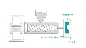
In the rubber to metal bonding process, the adhesive is applied to a properly prepared metal surface prior to molding. During curing, it undergoes chemical interaction with both the metal oxide layer and the rubber compound, forming a crosslinked structure that stabilizes the interface.

The performance of Chemlok adhesive systems depends on controlled surface roughness, surface cleanliness, coating thickness and curing parameters. When properly applied, the bonded interface fails cohesively within the rubber rather than adhesively at the metal boundary, indicating interfacial stability.

Chemlok Adhesive Systems Used in Rubber to Metal Bonding:

Adhesive Grade System Type Primary Function Typical Engineering Application
205 / 207 Primer Metal surface activation layer Base layer in multi-coat rubber to metal bonding systems
220 Covercoat Elastomer bonding layer General purpose rubber-to-metal molding applications
250 One-Coat Combined primer + covercoat system Process efficient bonding of multiple elastomer types
607 / 608 One-Coat / Two-Coat Silicone-compatible bonding system Silicone to metal assemblies requiring thermal stability
5151 Covercoat Fluoroelastomer bonding Viton® (FKM) to metal components exposed to chemicals or heat
CB150 Cold-Bond System Ambient-temperature bonding Rubber repair, pulley lagging, non-vulcanized bonding

Role Of Chemlok Adhesive In Rubber To Metal Bonding:

Chemlok adhesive defines how the bonded interface behaves during molding and under service load. In production rubber-to-metal molding, its role is determined by interfacial strength, stress transfer behaviour and long-term stability.

  • Interfacial Bond Formation During Vulcanization.

Chemlok adhesive governs how the interface develops when the elastomer cures against the prepared metal insert. Under heat and pressure, the adhesive reacts with the metal oxide surface while integrating into the rubber crosslink network. Uniform film thickness and proper flash-off ensure consistent interfacial development across the insert geometry. If this reaction is incomplete, the bond may appear acceptable initially but degrade under operational load.

In bonded suspension bushings, inadequate interfacial development often results in early edge separation during torsional cycling rather than immediate rubber failure.

  • Metal Surface Anchorage Stability.

After grit blasting and surface activation, the primer establishes mechanical and chemical anchorage to the substrate. This anchorage resists shear stress generated during deformation and vibration. Variations in surface cleanliness or coating consistency directly influence anchorage stability. Localised weak zones typically become initiation points for delamination.

In over moulded steel sleeves, bond degradation frequently begins at radius transitions where anchorage coverage is inconsistent.

  • Stress Distribution Across Dissimilar Materials.

Rubber exhibits elastic strain under load, while metal maintains rigidity. The adhesive layer forms a transitional interphase that distributes strain between these materials rather than allowing stress to concentrate at a single boundary. This reduces localised strain accumulation at insert edges and geometric Proper stress distribution improves resistance to crack initiation under dynamic conditions.

In engine mounts subjected to cyclic compression, inadequate stress transition at the interface can shorten fatigue life despite acceptable static peel strength.

  • Differential Thermal Expansion Accommodation.

During curing and service exposure, rubber and metal expand and contract at different rates due to differences in their coefficients of thermal expansion. The adhesive must maintain bond integrity while accommodating this dimensional mismatch. Residual shear stress develops as the assembly cools from cure temperature, and repeated heating intensifies this effect. Stability under thermal cycling is therefore dependent on adhesive flexibility and anchorage balance.
Under-hood bonded components exposed to repeated temperature variation often exhibit interfacial micro-cracking when differential thermal expansion is not properly managed.

  • Load Transfer Integrity.

Bonded assemblies must transmit tensile, compressive and torsional loads without relative movement between materials. The adhesive ensures effective force transfer from elastomer body to metal insert across the entire contact area. Weak or uneven interfacial regions result in stress concentration and progressive degradation under load. Load transfer stability is essential for maintaining dimensional and functional reliability.

In torque-loaded bonded sleeves, insufficient interfacial load transfer can lead to rotational slip rather than cohesive rubber deformation.

  • Cohesive Failure Hierarchy Control.

A correctly engineered rubber-to-metal bond exhibits cohesive rubber failure rather than adhesive separation at the metal boundary. This confirms that interfacial strength exceeds the cohesive strength of the elastomer matrix. Adhesive performance influences this strength hierarchy through proper reaction, anchorage and curing discipline. Validation testing relies on this failure mode to confirm bond reliability.

During peel testing of vibration isolators, rubber-tearing failure indicates correct interfacial integration, whereas clean metal exposure signals adhesive instability.

  • Fatigue Resistance Under Cyclic Loading.

Repeated compression, torsion and vibration create micro-movement at the bonded interface. The adhesive layer resists crack initiation and slows propagation by maintaining interfacial cohesion under cyclic stress. Fatigue performance depends on uniform bonding across stress-sensitive regions. Even minor inconsistencies can accelerate progressive delamination.

In high-cycle vibration dampers, interfacial fatigue degradation often determines service life more than bulk rubber hardness or stiffness.

  • Environmental and Corrosion Protection at the Bond Line.

Moisture ingress, oils and chemical exposure can initiate corrosion beneath unstable bond lines. The adhesive contributes to sealing the interface and limiting environmental penetration when properly applied with compatible primer systems. Protection of the metal surface prevents progressive weakening of adhesion over time. Long-term durability depends on maintaining this protected boundary.

Industrial rollers operating in wash-down environments frequently fail due to corrosion-driven delamination when bond-line sealing is inadequate.

Industrial Applications of Chemlok-Based Rubber to Metal Bonded Parts

Chemlok-based rubber to metal bonded parts is used in applications where controlled load transfer, vibration isolation and long-term interfacial stability are critical. The adhesive enables structural integration between elastomer and metallic insert during rubber to metal molding ensuring that bonded assemblies function as mechanical components rather than layered attachments.

  • Automotive Suspension & Engine Mounts

In bonded suspension bushings and engine mounts, elastomer components must absorb torsional and compressive loads while remaining anchored to steel sleeves or housings. The chemlok rubber to metal adhesive ensures that cyclic deformation results in cohesive rubber strain rather than adhesive separation. Fatigue resistance under high-cycle vibration determines service life.

  • HVAC Vibration Isolation Systems

HVAC isolators rely on bonded elastomer-metal assemblies to reduce transmitted vibration and noise. These systems operate under repeated compression and moderate thermal variation. Stable interfacial adhesion prevents edge separation and maintains dimensional alignment of metal mounting points.

  • Marine & Offshore Equipment

Marine bonded components are exposed to moisture, salt and thermal fluctuation. Adhesive systems must resist corrosion induced delamination and maintain anchorage stability over extended intervals. Surface preparation discipline and corrosion-resistant substrates are critical in these environments.

  • Aerospace Elastomeric Isolators

Aerospace applications demand predictable behaviour under dynamic loading and temperature variation. Bonded isolators must withstand vibration without progressive interfacial degradation. In such systems, cohesive rubber failure during validation testing confirms correct adhesive integration.

  • Chemical & High-Temperature Assemblies

Fluoroelastomer (FKM) bonded sleeves and mounts used in chemical processing equipment require thermal and chemical resistance. Specialized Chemlok grades compatible with FKM compounds ensure that bond integrity is maintained under aggressive exposure conditions.

Across industries, performance reliability of rubber to metal bonded components depends not only on elastomer formulation but on consistent adhesive control and process repeatability.

Chemlok adhesive plays a defining role in the rubber to metal bonding process by transforming two mechanically dissimilar materials into a structurally integrated assembly. Its function extends beyond initial adhesion to controlling interfacial stability, stress transfer behaviour, thermal mismatch accommodation and long-term fatigue resistance. When surface preparation, coating application and curing parameters are disciplined and repeatable, the bonded interface exhibits cohesive rubber failure rather than adhesive separation, confirming interfacial integrity. In engineered rubber to metal bonded components, reliable performance is therefore not achieved by adhesive selection alone but by precise control of the interphase that Chemlok systems are designed to create during vulcanization.

Why Partner with Schilthorn for Rubber to Metal Bonded Components

With over 18+ years of precision manufacturing experience, Schilthorn Precision Engineering delivers rubber to metal bonded components in millions. Our controlled rubber to metal molding processes, validated adhesive application protocols, and calibrated inspection systems including CMM-based dimensional verification ensure tolerance integrity, geometric consistency, and predictable interfacial performance across production batches. By combining disciplined surface preparation, process-controlled vulcanization, and repeatable manufacturing stability, we help engineering teams achieve cohesive bond reliability rather than variable adhesion outcomes in demanding industrial applications. Have a rubber metal components requirement? Share your technical drawings or specifications with our engineering team to discuss your next rubber to metal bonding project. Contact Us Now

Best Precision Engineering Companies in India: A Comprehensive Review

India’s precision engineering landscape has shifted considerably over the past two decades. As CNC manufacturing matured and automation standards strengthened, the expectations placed on dimensional control, repeatability, and inspection depth increased across aerospace, automotive, HVAC, and industrial supply chains.

Within this evolving environment, precision parts manufacturing companies in India are no longer evaluated solely on machine capacity. Multi-axis CNC platforms, structured quality systems, and coordinate measuring machines have become baseline requirements. The real differentiator lies in how consistently geometric tolerances are controlled and validated across production runs.

In high precision applications tolerance capability is not a marketing claim it is a measurable parameter. Machine count does not equal dimensional discipline. Process stability, inspection integrity, and geometric control ultimately determine whether a precision engineering company can support demanding performance environments.

Top 10 Best Precision Parts Manufacturing Companies in India

  • Schilthorn Precision Engineering Pvt. Ltd.

Schilthorn Precision Engineering, is one of India’s leading precision parts manufacturing company with advanced machining infrastructure, supporting Aerospace, HVAC, Automotive, and Industrial Equipment. Schilthorn’s manufacturing process is structured around controlled dimensional performance, process stability, and geometric repeatability to achieve high performance precision machined parts.

Its machining operations are supported by multi-axis CNC Milling Centres enabling them for high-precision component production across varied materials. There manufacturing focus extends from nominal size accuracy to controlled geometric tolerances including:

  • Flatness: ±0.01 mm across the full surface.
  • Circularity: ±0.01 mm for components as small as 2 mm in diameter.
  • Cylindricity: ±0.01 mm across the entire component length.
  • Parallelism: ±0.01 mm between datum and reference surface.
  • Perpendicular: 90° ± 0.01 mm between datum and axis.
  • Runout: Below 10 microns.

These tolerance parameters indicate machining capability within tightly regulated geometric control environments. Inspection protocols form an integrated part of the production workflow rather than a final stage validation step. Schilthorn is also equipped with advance inspection facility ranging from Non destructive testing to CMM machine and Vision Measuring Machine which ensures speed and scalability without any cycle time compromises.

  • Bharat Forge Ltd.: Operates as an integrated forging and machining manufacturer serving automotive, power generation, oil & gas, railways, and heavy engineering sectors. The company combines large-scale forging infrastructure with precision machining capabilities to deliver high-strength structural components. Its operations support both domestic and global OEM supply chains where material integrity, dimensional consistency, and production scalability are central requirements. The company’s manufacturing model majorly process integration from raw material processing through finished machined parts.
  • Sansera Engineering Ltd.: Manufactures complex precision machined components primarily for automotive and aerospace industries. Its product portfolio includes engine components, structural parts, and performance-critical assemblies requiring controlled geometric tolerances. The company supports regulated supply environments through structured quality management systems and CNC-based machining operations. Its production framework focuses on dimensional repeatability across medium- to high-volume programs.
  • Sundram Fasteners Ltd.: Are part of the TVS Group, produces precision-engineered components and fastening solutions for global automotive manufacturers. The company integrates high-volume production with machining operations to manufacture critical components used in engine and structural applications. Its manufacturing systems are aligned with automotive industry compliance standards, supporting traceability and batch-level consistency. The company serves both domestic and export markets through established supply chain networks.
  • INDO-MIM Ltd.: Specializes in metal injection molding and precision machined components for industries including medical devices, aerospace, automotive, and industrial equipment. The company combines powder metallurgy with secondary machining processes to produce intricate components featuring complex geometries. Its manufacturing approach supports applications where fine-detail precision and material performance are critical. INDO-MIM’s operational framework addresses both small-format and high-specification component requirements.
  • Maini Precision Products Ltd.: Manufactures precision-engineered components with a strong presence in aerospace and automotive supply chains. The company’s CNC machining operations support the production of complex parts requiring defined tolerance control and structured inspection systems. Its facilities are aligned with export-oriented manufacturing programs and regulated industry requirements. The company focuses on dimensional stability and production reliability across diversified component categories.
  • Aequs Ltd.: Operates within the precision components manufacturing segment, with a strong emphasis on aerospace supply programs. The company integrates machining, assembly, and manufacturing ecosystems designed to support compliance-driven industries. Its operations are structured around tolerance control, traceability, and documentation processes aligned with aerospace production standards. Aequs supports both domestic and international customers across regulated engineering environments.
  • Ramkrishna Forgings Ltd.: Manufactures forged and machined components for automotive, railway, and earthmoving sectors. The company integrates forging processes with secondary machining operations to produce load-bearing structural parts. Its manufacturing framework supports heavy-duty applications requiring material strength and dimensional reliability. Production systems are designed to manage large-volume industrial programs with consistent quality oversight.
  • Schaeffler India Ltd. / SKF India Ltd.: Are major providers of precision bearings and related mechanical components used in automotive, industrial, and energy applications. Their manufacturing operations focus on high-precision rolling elements, assemblies, and motion control components. These companies support global supply chains where tolerance accuracy, rotational stability, and material performance are essential. Their operational models are built around structured quality and compliance systems.
  • MTAR Technologies Ltd.: Manufactures high-precision components for nuclear, space, defense and clean energy sectors. The company supports critical engineering programs requiring tight dimensional control and adherence to strict performance standards. Its machining capabilities address complex geometries used in regulated environments. MTAR’s production systems are aligned with compliance intensive industries where reliability and traceability are mandatory.

How to Choose the Right Precision Engineering Company

Selecting a precision engineering company requires evaluation beyond visible infrastructure or production scale. The right partner is defined by dimensional control, process stability, and consistency under application-specific demands. A structured assessment helps reduce long-term operational risk and ensures alignment with performance expectations.

  • Tolerance Control: In precision engineering application achieving close tolerances is one of the key factors while selecting a precision machining supplier. User needs to review documented geometric tolerances such as flatness, circularity, cylindricity, parallelism, and runout Whether capability is within required tolerance ranges. More importantly, check for repeatability across production batches rather than achieved in isolated samples. Consistent tolerance retention under production load is a stronger indicator than single-part validation.
  • Delivery Lead Time: when looking for supplier, production cycle time and delivery lead time is one of the important factors. For certain industries such as automobile which works on JIT methodology maintaining a lower lead time is important. Project can get delayed due to extended timelines which impact on cost. Consider a supplier who can deliver in the best lead time without compromising on quality and cost.
  • Infrastructure: look for a supplier who has got various processes under one roof or within it’s supply chain. Precision machines need not only requires high precision CNC Turning and Milling centres but having supporting processes such as surface treatment, welding, & forging is also an added point. A supplier with such capabilities within your supply chain will add value and help you meet your timelines.
  • CNC & Process Stability: Assess whether multi-axis CNC systems are supported by structured programming workflows, tool management controls, and setup standardization. Process discipline determines stability under material variation and production scaling. Stable process parameters and controlled setups reduce dimensional drift during extended production cycles.
  • Quality Certifications: The certification such as ISO 9001, IATF 16949, AS9100, Or IRIS indicate structured quality management frameworks. While certification alone does not guarantee precision, it reflects traceability, documentation control, and corrective action protocols essential in regulated industries. Mature quality systems typically correlate with improved process accountability and audit readiness.
  • Inspection Systems: Evaluate whether coordinate measuring machines, surface finish validation tools, and calibrated instruments are integrated into the production workflow. Inspection should be integrated throughout the process, not limited to final-stage validation. Documented inspection checkpoints provide measurable assurance of dimensional conformity.
  • Production Reliability: Technical capability must be supported by delivery consistency and clear communication. Reliable manufacturers maintain stable production planning, documented quality records, and transparent technical coordination throughout project execution. Predictable lead times and controlled batch traceability contribute to long-term supply chain stability.
  • Industry Experience: last but not the least look for a supplier who have a domain expertise for your manufacturing needs. Each industry has it’s own requirement some require high volume with precision rest needs high precision with lower cost and faster delivery, supplier with vast experience can understand the nitty gritty of the industry and help you achieve your targets.

Why Choose Schilthorn Precision for Your Precision Manufacturing Needs.

With over 18+ years of experience in precision engineering, Schilthorn Precision Engineering Pvt. Ltd. operates within high precision manufacturing environments. Out state of the art infrastructure is designed for dimensional stability and geometric accuracy across industries such as aerospace, HVAC, automotive, and industrial applications. Our facility includes Milling, Turning, SPM’s, Turn-Mills, Forging, Welding, & Surface Treatment all under one roof. With our expertise we can achieve a geometric tolerance up to ±0.01 mm and runout control below 10 microns. Certified to ISO 9001 and AS9100 standards, Schilthorn maintains structured quality frameworks and traceability systems that ensure each precision machined component is validated against defined dimensional criteria before release, supporting performance reliability in demanding operational environments.

Why Rubber to Metal Bonding Fails, Common Challenges with Expert Solutions

Rubber to metal bonding is a controlled thermo-chemical joining method in which an elastomer is permanently attached to a metallic insert during vulcanization. Because the bonded interface cannot be inspected after curing, its performance depends entirely on disciplined surface preparation, adhesive control and process stability.

Metal-to-rubber bonding is technically challenging because it involves joining materials with fundamentally different mechanical and thermal characteristics. Elastomers deform elastically and exhibit high strain capability, while metals maintain rigid structural behaviour. Differences in modulus, surface energy and coefficient of thermal expansion create interfacial stress during curing and under service conditions. Maintaining a stable bond therefore requires strict control of surface condition, adhesive activation and curing parameters.

In precision-engineered components, interfacial separation reduces fatigue life and structural reliability. Bond failure is rarely caused by a single defect; it is typically the result of cumulative process imbalance. The following sections explain the common causes of rubber to metal bonding failure and the expert solutions required to prevent them.

Rubber to Metal Bonding Fails and Common Challenges with Expert Solutions

1. Metal Surface Contamination and Low Surface Energy:

The bonded interface begins at the metal surface. Adhesive primers require intimate molecular contact with a chemically active surface to develop stable adhesion. Residual oils, corrosion inhibitors, moisture films or handling contamination reduce surface energy and impair wetting. When wetting is incomplete, adhesive cannot penetrate micro-asperities effectively, resulting in localized weak zones at the primer metal interface. The common indicators and contributing factors are:

  • Visible oil smearing or uneven primer spread.
  • Water break test failure.
  • Delayed adhesive application after blasting.
  • Silicone contamination from compressed air systems.
  • Fingerprint contamination during handling.
  • Oxidation of inserts stored in humid conditions.

Engineering Solution:

Surface preparation must be treated as a controlled parameter within the rubber to metal bonding process. Degreasing should be validated through surface cleanliness testing. A defined blast-to-prime time window must be enforced to minimize oxide formation. Controlled storage and handling procedures reduce variability before adhesive application.

2. Inadequate or Excessive Surface Roughness

Mechanical anchoring between adhesive and metal depends on controlled surface roughness generated during abrasive blasting. A surface that is too smooth limits mechanical interlocking, while an excessively rough surface creates stress concentration points that weaken adhesion under cyclic load. Inconsistent roughness leads to variation in bond strength across rubber to metal bonded parts which includes factors such as:

  • Low bond strength despite proper adhesive use.
  • Smooth metal finish after blasting.
  • Integrated abrasive particles.
  • Variation in blasting pressure.
  • Reused or contaminated blasting media.
  • Inconsistent Ra measurements.

Engineering Solution:

Define and validate an optimal roughness range using profilometer measurement. Standardize blasting parameters and replace media regularly. Surface profile verification should be integrated into insert inspection before priming.

3. Adhesive Film Thickness Variation

Rubber to metal bonding relies on precise primer and cover coat thickness to transfer load effectively. A thin adhesive layer results in incomplete coverage, while excessive thickness may introduce internal stress and cohesive weakness. Thickness variation directly compromises the uniformity of rubber to metal bonded components.

  • Adhesive pooling or sagging.
  • Uneven spray patterns.
  • Improper viscosity due to dilution errors.
  • Inconsistent mixing ratios.
  • Clogged spray equipment.
  • No thickness validation checks.

Engineering Solution:

Monitor adhesive viscosity and solids content. Calibrate spray equipment to maintain uniform deposition. Perform periodic destructive thickness verification. Adhesive application must be treated as a measurable variable within the rubber to metal bonding process.

4. Incomplete Solvent Flash-Off

During rubber to metal molding, residual solvent trapped within the adhesive layer expands under heat, generating micro-voids or blistering. These voids reduce effective bonding area and act as crack initiation points. Environmental conditions strongly influence solvent evaporation behaviour.

  • Blistering after demoulding.
  • Bubbles at the interface during failure analysis.
  • Shortened flash-off time to increase output.
  • High humidity in coating area.
  • Thick adhesive layers.
  • Poor airflow during drying.

Engineering Solution:

Establish and validate defined flash-off times under controlled temperature and humidity. Ensure complete solvent evaporation before molding begins. Use forced-air drying where necessary to stabilize evaporation rates.

5. Adhesive Rubber Material Compatibility Mismatch

Chemical compatibility between adhesive and elastomer is essential for stable interfacial bonding. Mismatch in polarity, cure system or formulation chemistry weakens crosslink development at the interface. Blooming additives or plasticizer migration can form a barrier that prevents effective adhesion in rubber to metal bonded parts:

  • Clean adhesive surface after rubber separation (RC-type failure).
  • Visible blooming on rubber surface.
  • Change in rubber compound supplier.
  • Peroxide-cured elastomer paired with incompatible adhesive.
  • Excessive softener content.
  • Bond strength variation across rubber grades.

Engineering Solution:

Match adhesive chemistry with the rubber compound and cure system. Conduct compatibility trials before production. Limit blooming-prone ingredients. Validate bonding through peel or shear testing during development.

6. Cure Imbalance and Density Variation

Bond development depends on synchronized adhesive activation and rubber crosslinking. Under-curing reduces crosslink density and weakens cohesive strength, while over-curing may degrade elastomer properties. Thermal gradients within moulds can produce inconsistent cure across rubber to metal bonded components due to factors such as:

  • Hardness variation between cavities.
  • Reduced tensile strength.
  • Premature failure after aging.
  • Uneven platen temperature.
  • Cycle time reduction without validation.
  • Inconsistent rheometer results.

Engineering Solution:

Determine optimal cure parameters through rheometer testing. Conduct thermal mapping to ensure uniform heating. Avoid cycle time reduction without confirming full crosslink development. Validate bond performance after accelerated aging.

7. Molding Pressure and Flow Imbalance

Uniform pressure during rubber to metal molding ensures intimate contact between rubber and adhesive-coated inserts. Insufficient clamp force, poor venting or uneven flow can prevent full wetting of the bonding surface, creating localized weak regions, Common indicators and contributing factors:

  • Localized failure near gate areas.
  • Flash indicating poor sealing.
  • Trapped air pockets.
  • Inconsistent cavity pressure.
  • Poor venting design.
  • Flow shadow regions around inserts.

Engineering Solution:

Calibrate clamp force regularly. Optimize venting to prevent gas entrapment. Use flow simulation during mold design. Monitor cavity pressure during production to improve consistency.

8. Thermal Expansion Mismatch

Rubber expands and contracts at a rate significantly different from metal. During temperature cycling, differential expansion generates shear stress at the interface. Under cyclic mechanical loading, stress concentration at geometric transitions may initiate micro-separation in rubber to metal bonded components:

  • Failure after thermal cycling tests.
  • Delamination at sharp insert corners.
  • Cracks at geometric transitions.
  • Thin bonding areas.
  • High operating temperature fluctuations.
  • Repeated cyclic shear loading.

Engineering Solution:

Select elastomer grades suitable for operating temperature range. Incorporate adequate radii and bonding area in design. Conduct accelerated fatigue and thermal cycling tests during validation.

9. Environmental and Chemical Degradation

Service environments involving oil, humidity, ozone and elevated temperatures can degrade elastomer properties. Oil swelling alters stress distribution; heat aging increases stiffness and chemical attack weakens polymer chains. These changes shift load toward the interface and promote separation.

  • Increased hardness after aging.
  • Volume expansion after oil immersion.
  • Surface cracking from ozone exposure.
  • Reduced bond strength after thermal aging.
  • Exposure to aggressive chemicals.
  • Lack of environmental validation.

Engineering Solution:

Select rubber compounds compatible with service conditions. Conduct oil immersion, heat aging and humidity cycling tests during validation. Evaluate bond strength after environmental exposure to confirm long-term durability.

Rubber to metal bonding fails when surface stability, adhesive control, cure synchronization, molding balance or environmental compatibility are compromised. Reliable performance in rubber to metal bonded components depends on treating each stage of the rubber to metal bonding process as a measurable and controlled parameter. When surface preparation, material compatibility and thermal stability are disciplined and validated, bond strength becomes repeatable, durable and resistant to service-induced degradation.

10. Insert Dimensional Tolerance

Rubber to metal bonding is not only a chemical process; it is also a dimensional interface system. Variations in insert geometry, concentricity, flatness or surface parallelism directly influence adhesive distribution and stress transfer. If metallic inserts fall outside machining tolerance limits, rubber flow during rubber to metal molding may become uneven, resulting in localized thin bond areas or incomplete wetting.

Even small deviations in insert thickness or misalignment within the cavity can create non-uniform compression and pressure gradients during vulcanization. These variations alter adhesive film behaviour and crosslink development. In precision assemblies’ machining tolerance may shift stress concentration to specific regions of rubber to metal bonded parts, increasing the likelihood of delamination under cyclic loading. Common Indicators and Contributing Factors:

In precision assemblies’ machining tolerance:

  • Localized bond failure at one edge of insert.
  • Variation in bond strength across identical batches.
  • Uneven rubber flash distribution.
  • Insert wobble or misalignment during molding.
  • Out-of-spec flatness or concentricity.
  • Inconsistent insert positioning in multi-cavity tools.

Engineering Solution:

Metal inserts used in rubber to metal bonded components must comply with defined dimensional tolerances and geometric controls. Flatness, concentricity and thickness should be verified prior to molding. Insert positioning fixtures must ensure repeatable alignment inside the mold cavity. Precision control of insert geometry is as critical as adhesive chemistry in achieving stable bond performance.

Why Choose Schilthorn Precision Engineering to Controls These Bonding Failures

At Schilthorn Precision Engineering, rubber to metal bonding is treated as an integrated engineering system rather than an isolated adhesive operation. Surface preparation, insert geometry, adhesive application, controlled moulding and cure synchronization are managed as measurable process parameters to prevent the failure mechanisms discussed above. From validated surface conditioning and primer systems to stable compression and transfer moulding under defined cure cycles, each stage of the rubber to metal bonding process is controlled to ensure consistent adhesion strength and structural reliability. Supported by CMM-verified inspection and ISO 9001 & AS9100 certified quality systems, rubber to metal bonded components is produced under disciplined process control to minimize variability and enhance long-term fatigue performance.

Rubber to Metal Bonding Process: A Step-by-Step Technical Guide

What is Rubber to Metal Bonding

Rubber to metal bonding is an engineered interfacial joining system in which an elastomeric material is permanently attached to a metallic substrate to form a unified functional assembly. Unlike simple adhesive attachment, this method integrates surface chemistry, material compatibility and controlled vulcanization to create a structural interface capable of transferring load, absorbing vibration and maintaining dimensional stability under service conditions.

In engineered applications, the bonded interface is not merely a connection layer. It becomes a stress-transmitting region where differences in modulus, thermal expansion and deformation behaviour must be accommodated without separation or fatigue failure. The performance of rubber to metal bonded systems therefore depends on coordinated control of material selection, surface preparation, adhesive chemistry, moulding conditions and cure parameters. These assemblies may be produced as bonded bushings, vibration isolators, or as integrated rubber injection moulding components where metal inserts are over moulded within a controlled manufacturing cycle.

Rubber to metal bonding is a critical manufacturing process used in vibration isolation, sealing systems and structural assemblies across automotive, aerospace and industrial sectors. The rubber to metal bonding process integrates surface preparation, adhesive chemistry and controlled vulcanization to create durable rubber to metal bonded components capable of withstanding dynamic loads and environmental stress.

Types of Rubber to Metal Bonding

Rubber-to-metal bonding is an engineered interfacial joining system designed to create composite components capable of transferring mechanical load, absorbing vibration, and accommodating differential thermal expansion between elastomers and metallic substrates. The integrity of the bond depends on interfacial adhesion mechanisms, surface energy compatibility, curing chemistry and stress distribution across the bonded region. Bonding systems are classified according to the dominant adhesion mechanism governing load transfer at the interface.

1. Chemical Bonding (Adhesive-Mediated Co-Vulcanization)

Chemical bonding is the most reliable method for structural and load bearing applications. The metal surface is first cleaned and roughened, then coated with a primer and cover adhesive designed to react with the elastomer during vulcanization. During curing, the rubber crosslinks internally while simultaneously forming a chemical bond at the adhesive interface. This creates a strong and durable connection capable of resisting shear, tensile and peel forces.

  • Requires degreasing, grit blasting, and controlled surface roughness.
  • Primer improves adhesion to metal; cover coat bonds with rubber compound.
  • High shear and peel strength.
  • Strong fatigue resistance under cyclic loading.
  • Used in structural mounts, bushings, and vibration isolation systems.

2. Mechanical Bonding (Geometric Interlocking)

Mechanical bonding relies on physical retention rather than chemical adhesion. The metal part is designed with grooves, undercuts, perforations or knurled surfaces. During moulding, uncured rubber flows into these features and locks into place after curing. The bond strength comes from mechanical anchoring and friction rather than molecular interaction.

  • No adhesive system required.
  • Uses retention features such as grooves, undercuts and perforations.
  • Moderate strength compared to chemical bonding.
  • Lower fatigue resistance in dynamic applications.
  • Suitable for low-load or non-structural components.

3. Direct Bonding (Reactive Adhesive-Free Bonding)

Direct bonding uses specially formulated rubber compounds that can bond directly to the metal surface during vulcanization. In this method, no separate primer or cover adhesive layer is applied. The rubber compound reacts with the metal oxide layer under controlled temperature and pressure conditions.

  • Eliminates separate adhesive application steps.
  • Requires strict control of surface cleanliness.
  • Limited to compatible rubber-metal combinations.
  • Suitable for high-volume production.
  • Reduces process complexity when properly controlled.

4. Cold Bonding (Post-Vulcanization Adhesive Bonding)

Cold bonding is performed after the rubber component has already been cured. The rubber and metal surfaces are cleaned and roughened, and an adhesive is applied at room or moderate temperature. Since the rubber is not curing simultaneously with the adhesive, the bond strength is typically lower than co-vulcanized systems.

  • Used for repair, retrofit or secondary assembly.
  • No simultaneous vulcanization.
  • Lower fatigue resistance under dynamic loads.
  • Highly dependent on surface condition and adhesive curing.
  • Not recommended for high-load structural use.

5. Insert Moulding (Metal Integration)

Insert moulding involves placing a pre-machined metal component inside the mould before rubber injection or compression moulding. During vulcanization, the rubber flows around the insert and bonds through chemical, mechanical or hybrid mechanisms depending on surface treatment. This method allows accurate positioning of the metal within the rubber body and ensures controlled load transfer within the assembly.

  • Enables dimensional control of metal insert position.
  • Can combine adhesive bonding and mechanical retention.
  • Suitable for vibration control and isolation systems.
  • High repeatability in production.
  • Requires precise insert placement and controlled mould flow.

Materials Used in Rubber to Metal Bonding

Rubber-to-metal bonding combines selected elastomers with compatible metal substrates using controlled adhesive systems and moulding techniques. Material selection directly influences bond strength, fatigue resistance, chemical stability and long-term durability.

Common Elastomers Used in Rubber-to-Metal Bonding

Elastomer Key Properties Typical Applications
Natural Rubber (NR) High elasticity, excellent resilience, strong fatigue resistance Shock absorbers, vibration mounts
Nitrile Rubber (NBR) Oil and fuel resistance Automotive seals, engine components
EPDM Weather, ozone, and water resistance HVAC systems, outdoor components
Silicone (VMQ) High-temperature stability, flexibility Electrical insulation, thermal components
Fluor elastomer (FKM / Viton) High heat and chemical resistance Chemical processing, high-temp sealing
Neoprene (CR) Balanced flexibility and chemical resistance General industrial bonded components

Common Metal Substrates

Metal Key Characteristics Typical Use
Carbon Steel High strength, cost-effective Structural bonded mounts
Aluminium Lightweight, corrosion resistant Automotive and aerospace assemblies
Stainless Steel Superior corrosion resistance Marine and chemical environments
Brass / Copper Good sealing compatibility Specialized sealing components

Adhesives, Primers & Process Materials

Material / System Function
Chemlok Adhesives Two-coat primer and cover system for strong rubber-metal adhesion
Phenolic Resin Systems Heat-resistant bonding agents
Silane Primers Used for silicone-to-metal bonding
Zinc Phosphate Treatment Surface preparation for improved adhesion
Injection / Transfer / Compression Moulding Controlled moulding processes for uniform bonding
Over moulding Encapsulates metal inserts within rubber
Foam Tapes (e.g., VHB) Used for secondary bonding of pre-cured rubber

Step-by-Step Rubber to Metal Bonding Process

Rubber-to-metal bonding is not a single operation. It is a controlled manufacturing sequence where surface condition, adhesive chemistry and vulcanization must function as an integrated system. Bond strength is determined less by adhesive choice alone and more by the stability and repeatability of each production stage.

1. Part Design and Engineering Review

Part Design and Engineering Review

Before production begins, engineers evaluate insert geometry, material selection and mould interaction. Insert shape influences stress distribution, rubber flow, and flash control. The metal substrate must match service conditions, while the elastomer must be compatible with both operating environment and bonding system. Key considerations include:

  • Insert orientation within the mould
  • Positive shut-off to prevent flash
  • Selection of elastomer (e.g., NBR, EPDM, FKM)
  • Selection of substrate (steel, aluminum, brass)

Insert thickness and edge geometry must also be reviewed to prevent stress concentration at the bond line. Sharp transitions between bonded and unbonded regions can increase peel stresses during service. Engineers may incorporate radii or bonding margins to reduce interfacial stress gradients.

Dimensional tolerances of stamped or machined inserts must be controlled to ensure repeatable mould positioning. Variations in insert flatness or thickness can lead to uneven rubber flow and inconsistent bonding pressure.

Example: In an engine mount assembly, carbon steel inserts are selected for structural strength, while NBR is chosen for oil resistance. The insert is designed with controlled shoulders to allow positive mould shut-off and minimize flash during compression moulding. The bonding margin is defined to prevent edge peeling during cyclic engine vibration.

2. Metal Surface Conditioning

Metal Surface Conditioning

Surface preparation establishes the bonding interface. The metal must be free from oil, oxide layers, machining debris and moisture to ensure proper adhesive wetting. Surface energy and surface profile directly influence bond consistency. Preparation typically includes:

  • Solvent or alkaline degreasing
  • Abrasive blasting (commonly aluminum oxide)
  • Optional chemical conversion coating
  • Complete drying before priming

Surface roughness must be uniform across the bonding area. Inconsistent blasting pressure or media size can create localized weak bonding zones. Surface cleanliness is often verified visually or through controlled process validation rather than relying solely on operator judgment.

Environmental exposure between blasting and priming must be minimized. Humidity can accelerate surface oxidation, especially on carbon steel substrates. In controlled production environments, inserts may be stored in low-humidity areas before adhesive application.

Example: For suspension bushings using steel inserts, grit blasting is controlled to Ra 2–5 µm and primer is applied within a defined time window to prevent surface oxidation before adhesive coating. Inserts exposed beyond this window are re-blasted to restore surface condition before bonding.

3. Adhesive Primer System Application

Bonding systems commonly use a two-coat system consisting of a primer and a cover adhesive. The primer promotes adhesion to the metal oxide layer, while the cover coat chemically reacts with the rubber during curing. Critical controls include:

  • Adhesive viscosity and mixing ratio
  • Film thickness control
  • Application method

Spray application: Adhesive is atomized and evenly deposited onto the metal surface using controlled air or pressure systems for uniform coating thickness.

Spray application

    • Dip application: The metal insert is immersed into the adhesive bath to achieve complete and consistent surface coverage.Dip application
    • Brush application: Adhesive is manually applied using a brush, typically for low-volume production, touch-up, or localized bonding areas.Brush application
  • Controlled drying or baking cycle

Coating uniformity across complex insert geometries must be maintained. Masking may be used to prevent adhesive application on non-bonding areas. Film thickness is typically controlled through calibrated spray systems or controlled dipping cycles to ensure repeatability.

Drying temperature and duration must allow complete solvent evaporation without premature curing of the adhesive layer. Excessive drying temperature can reduce reactivity during vulcanization.

Example: In vibration isolator production, a two-coat adhesive is spray-applied and oven-dried at controlled temperature to ensure solvent evaporation before the insert enters the moulding press. Adhesive film thickness is periodically verified to maintain consistent bond performance across production batches.

4. Insert Placement and Moulding Process

Insert Placement and Moulding Process

After adhesive preparation, the insert is positioned within the mould cavity. Insert alignment must remain stable during rubber flow to maintain uniform stress distribution. In rubber to metal moulding, rubber is introduced through three primary moulding methods depending on production volume, insert geometry and bonding requirements

  1. Compression Moulding:Pre-measured rubber is placed directly into the mould cavity and compressed under heat and pressure. Suitable for low-to-medium volume parts and metal insert components.
  2. Transfer Moulding:Rubber is placed in a transfer chamber and forced into the mould cavity under pressure. This method provides better control for complex geometries.
  3. Injection Moulding:Rubber is plasticized and injected into the mould under high pressure. Ideal for high-volume, repeatable production.

Moulding stability including temperature, pressure, venting and clamp force determines uniform adhesive contact and bond continuity. Air entrapment or uneven cavity fill can reduce effective bonding area and compromise structural reliability.

5. Vulcanization (Curing)

Vulcanization (Curing)

During moulding, heat and pressure initiate rubber crosslinking and activate the bonding system. The adhesive reacts with the elastomer to form a permanent bond at the interface. Cure cycle parameters include:

  • Temperature
  • Time
  • Pressure

Cure time must be matched to compound formulation and part thickness. Thicker sections may require extended cure times to ensure full crosslink development throughout the elastomer body. Uneven mould heating can create localized under-cured regions.

Pressure must remain sufficient to maintain intimate contact between rubber and adhesive-coated insert throughout the cure cycle. Loss of pressure or premature mould opening can disrupt bond formation.

Example: For NBR bonded to steel, cure temperatures typically range between 150–180°C. Deviations from validated cure cycles may affect both rubber hardness and bond reliability. In high-load mounts, cure parameters are validated through trial production runs to ensure consistent crosslink density and adhesion strength.

Quality Inspection and Testing

Quality validation in rubber-to-metal bonding is centred on verifying bond integrity, dimensional stability, and manufacturing consistency. The objective is not only to confirm initial adhesion strength but also to ensure that the bonded interface performs reliably under expected service loads and environmental conditions. Testing methods are selected based on application requirements, load direction, and regulatory standards.

Peel Testing: 

Peel testing evaluates the bond’s resistance to separation under progressive tensile loading at a defined angle (commonly 90° or 180°). This method is particularly useful for flexible assemblies where peel stresses may develop during service. Peel testing provides practical insight into interfacial continuity and identifies weak bonding regions caused by inconsistent surface preparation or adhesive application. The test measures:

  • Peel strength (force per unit width).
  • Failure mode (adhesive, cohesive, or substrate).
  • Uniformity of bond along the interface.

Shear Testing: 

Shear testing determines the bond’s ability to resist forces acting parallel to the bonded interface. Since many bonded components primarily experience shear loading in service (e.g., bushings, mounts, isolators), this test is critical for structural validation. The test evaluates:

  • Maximum shear load capacity.
  • Elastic deformation before failure.
  • Stability under sustained or cyclic loading.

Adhesion Strength Evaluation:

 Adhesion strength testing quantifies the force required to separate rubber from metal under controlled laboratory conditions. It is often performed using tensile pull-off methods or standardized destructive tests. Beyond numerical strength values, inspection focuses on:

  • Location of failure (interface vs rubber matrix).
  • Consistency across multiple production samples.
  • Correlation with process parameters.

Visual Inspection: 

Visual inspection remains a fundamental quality control step. Trained inspectors assess:

  • Surface coverage of adhesive layers.
  • Presence of voids, air entrapment or incomplete fill.
  • Edge separation or flashing irregularities.
  • Surface contamination or oxidation.

Environmental validation: 

Environmental validation tests assess bond performance under simulated service conditions without entering detailed failure analysis. These may include:

  • Heat aging exposure.
  • Oil or chemical immersion.
  • Humidity cycling.
  • Thermal cycling within specified ranges

The goal is to confirm bond stability under anticipated environmental stresses rather than conduct root-cause failure investigation. Post-exposure mechanical testing verifies whether adhesion strength remains within defined acceptance limits.

Consistent quality in rubber-to-metal bonding is achieved only when surface preparation, adhesive application, moulding control and cure parameters operate within defined and repeatable manufacturing limits. Testing serves as both verification and feedback, ensuring that process discipline translates into durable interfacial performance.

Applications of Rubber-to-Metal Bonded Components Across Industries

Rubber-to-metal bonded components, including engineered rubber to metal bonded parts, are used wherever vibration isolation, sealing integrity or controlled flexibility must coexist with structural stability. Their performance depends on material compatibility, load path design and environmental resistance.

  • Automotive: Engine mounts, suspension bushings and vibration isolators rely on bonded assemblies to absorb dynamic loads while maintaining alignment under thermal cycling and oil exposure.
  • Marine: Propulsion mounts and corrosion-resistant isolators operate under continuous moisture exposure and salt-laden environments, requiring stainless or treated substrates.
  • HVAC Systems: Bonded dampers and vibration pads reduce mechanical transmission between compressors and structural frames while resisting temperature fluctuation and humidity.
  • Heavy Equipment: Construction and mining machinery use bonded bushings and isolators to manage shock loading and high cyclic stress in abrasive environments.
  • Aerospace: Precision isolation components and control system mounts require tight dimensional control and stable performance across wide temperature ranges.
  • Chemical Processing: Sealing systems and bonded liners must withstand aggressive fluids, high temperatures and sustained mechanical stress without interfacial degradation.

Rubber to metal bonded parts are widely used in vibration isolation, sealing systems and structural support applications where dynamic load transfer and environmental durability are critical..

Why Choose Schilthorn Precision for Rubber-to-Metal Bonded Components? 

With over 18+ years of precision manufacturing expertise, Schilthorn Precision Engineering Pvt. Ltd. delivers rubber-to-metal bonded components engineered for structural reliability and long-term performance. Our process integrates precision insert machining, controlled surface conditioning, Nylox and advanced surface treatments where required, validated primer and adhesive systems, and stable compression or transfer moulding under defined cure parameters. Backed by CMM-verified inspection and ISO 9001 & AS9100 certified quality systems, every bonded assembly is produced within controlled tolerance limits to ensure consistent adhesion strength and dimensional accuracy across production runs.

What is Thermal Expansion? A Precision Engineer’s Guide to Managing Heat

What Is Thermal Expansion?

Thermal expansion is the dimensional change that occurs in a material when its temperature varies. It is a fundamental thermophysical property of solid engineering materials and arises from atomic-level interactions within the material structure.

As temperature rises, atomic vibration amplitude increases, because interatomic bonding forces are inherently asymmetric, the average spacing between atoms expands with thermal energy. This change in mean interatomic distance produces measurable dimensional growth at the macroscopic scale.

Thermal expansion is not a material defect or instability. It is an inherent and predictable material characteristic that can be mathematically modelled. The extent of expansion depends on:

  • Material composition
  • Bonding structure
  • Crystal lattice arrangement
  • Temperature range
  • Phase stability

In engineering systems, thermal expansion influences structural alignment, stress development, tolerance accumulation and assembly compatibility. Its behaviour is governed by the material’s coefficient of thermal expansion (CTE), which defines the proportional relationship between temperature change and dimensional response.

Understanding what thermal expansion is in precision engineering requires examination of its physical mechanism, mathematical representation and material dependence across structural metals and engineering alloys.

What Is the Coefficient of Thermal Expansion (CTE)?

The coefficient of thermal expansion (CTE) is a fundamental thermophysical property that quantifies how much a material changes dimension in response to temperature variation. It defines the proportional relationship between temperature change and resulting dimensional strain in a solid material.

For solids undergoing uniform heating within standard engineering temperature ranges, dimensional growth is approximately linear with temperature. This proportional behaviour is represented through the linear coefficient of thermal expansion. The linear approximation remains valid within moderate temperature limits, before material behaviour approaches phase transformation, microstructural change or high-temperature nonlinearity.

The linear expansion relationship is expressed as:

ΔL=α⋅L⋅ΔT

Where:

  • ΔL = change in length.
  • α = linear coefficient of thermal expansion.
  • L = original length.
  • ΔT = temperature change.

The coefficient α represents the fractional increase in length per unit length for each degree of temperature rise. It is typically expressed in:

  • µm/m·°C
  • ×10⁻⁶ /°C

For example, if a material has a CTE of 12 µm/m·°C, it will expand by 12 micrometres for every metre of length for each 1°C increase in temperature.

Physical Meaning of CTE:

CTE does not describe total expansion directly. It describes sensitivity to temperature. Materials with higher CTE values respond more strongly to temperature variation, while materials with lower CTE values exhibit greater dimensional stability.

The magnitude of CTE is influenced by:

  • Interatomic bonding strength.
  • Crystal lattice structure.
  • Alloy composition.
  • Phase behaviour.

Materials with stronger atomic bonding generally exhibit lower expansion rates because atomic spacing changes less with increasing thermal energy.

Worked Calculation Example

Consider a 500 mm long steel bar with a linear CTE of 12 µm/m·°C.
If the temperature increases by 30°C:

ΔL=12×0.5×30

ΔL=180 µm

The bar will increase in length by 0.18 mm.

While this dimensional change may appear small, it becomes significant in systems requiring tight geometric control or dimensional compatibility between multiple components.

Types of Thermal Expansion

Thermal expansion in solid materials is classified based on how dimensional change occurs relative to geometry and temperature distribution. This classification allows engineers to distinguish between uniform dimensional growth and thermally induced geometric distortion.

Linear Expansion

Linear expansion is a dimensional change along a single axis when a material experiences uniform temperature variation. Every linear dimension length, diameter, thickness or spacing increases proportionally to the temperature change.

For example, if a 1-metre-long steel bar is uniformly heated, its total length increases while its geometric form remains unchanged. The expansion occurs equally along the entire axis.

Linear expansion directly affects:

  • Overall length.
  • Shaft diameters.
  • Bore sizes.
  • Plate thickness.
  • Feature spacing.

Because engineering tolerances are typically defined in linear units, linear expansion forms the basis of most dimensional calculations.

Volumetric Expansion

Volumetric expansion refers to the overall change in volume of a material due to temperature rise. In isotropic solids subjected to uniform heating, expansion occurs simultaneously in all three spatial directions.

As each linear dimension increases, the total volume increases accordingly. While the shape of the component may remain geometrically similar, its mass distribution and internal stress state may change slightly depending on constraints.

Volumetric expansion becomes particularly relevant in:

  • Large structural blocks.
  • Cast components.
  • Pressure-containing vessels.
  • Thick-section parts.

Differential Expansion

Differential expansion occurs when temperature distribution is not uniform or when materials with different thermal expansion characteristics are joined together.

Unlike uniform linear expansion, differential expansion produces uneven strain within a component or assembly. This can result in:

  • Warping
  • Bending
  • Internal stress
  • Geometric distortion

If one side of a metal plate experiences higher temperature than the opposite side, the hotter region expands more, causing curvature. Similarly, when two bonded materials with different coefficients of thermal expansion are heated, each attempt to expand by a different amount. Because they are constrained, internal stresses develop at the interface.

Differential expansion is often more structurally significant than uniform expansion because it affects geometric relationships rather than simply increasing size.

Thermal Expansion Coefficients of Common Engineering Materials

The linear coefficient of thermal expansion (CTE) varies significantly across materials. The following values represent approximate average linear CTE values near room temperature (~20°C). Actual values vary with temperature range, heat treatment condition and alloy composition.

Approximate CTE Values (µm/m·°C at ~20°C)

Material Linear CTE (µm/m·°C) Material Category
Fused Quartz 0.5 Ultra-Low Expansion
Invar (Fe–36Ni) 1.2 Low Expansion Alloy
Tungsten Carbide 4.5 Hard Composite
Titanium (Ti-6Al-4V) 8.6 Aerospace Alloy
H13 Tool Steel 10.4 Tool Steel
Carbon Steel (1020) 11.7 Structural Steel
304 Stainless Steel 16.0 Austenitic Stainless
303 Stainless Steel 17.3 Austenitic Stainless
17-4 PH Stainless Steel 10.8 Precipitation-Hardened
Inconel 718 13.0 Nickel Alloy
6061 Aluminium 23.6 Aluminium Alloy
7075 Aluminium 23.6 Aluminium Alloy
Magnesium 26.0 Light Metal
PEEK (Virgin) 50.0 Engineering Polymer
PTFE (Virgin) 120–140 Fluoropolymer
Nylon 90.0 Engineering Polymer

 Interpretation of Material Differences

Several important engineering observations can be made:

  • Aluminium expands approximately twice as much as carbon steel for the same temperature change.
  • Austenitic stainless steels exhibit higher expansion than carbon steels due to their crystal structure.
  • Titanium alloys demonstrate comparatively lower expansion among structural metals.
  • Invar is engineered specifically for dimensional stability in precision instrumentation.
  • Engineering polymers expand six to nine times more than common metals.

The difference between 12 µm/m·°C and 23 µm/m·°C becomes significant over long component lengths or moderate temperature variation. For a 1 metre component exposed to a 40°C change:

  • Carbon steel expands ≈ 480 µm
  • Aluminium expands ≈ 944 µm
  • PTFE expands several millimetres

This variation directly influences assembly design, stress development and dimensional compatibility.

Major Causes of Thermal Expansion in Machining

Thermal expansion occurs when heat introduced into the machining system causes dimensional change in the workpiece, tooling or machine structure. In high-precision applications, where tolerances are often below a few microns, even small temperature variations can lead to measurable dimensional drift. Thermal expansion is driven by multiple heat sources acting simultaneously throughout the machining cycle.

  • Cutting Action and Friction:

The interaction between the cutting tool and the workpiece generates heat due to material deformation and friction. High cutting speeds and materials with poor thermal conductivity, such as titanium and nickel-based alloys, create localised hot zones that cause temporary workpiece expansion. During high-speed turning of a titanium shaft, the outer surface temperature may rise significantly above the core, resulting in measurable diameter growth while machining is in progress.

  • Spindle and Drive System Heat:

Motorised spindles, bearings and drive systems generate heat during operation. This heat propagates through machine structures, causing axial and radial growth that directly affects tool positioning accuracy. In long-duration milling cycles, gradual spindle warming can shift tool position by several microns, altering feature depth or hole location despite unchanged program coordinates.

  • Axis Motion and Mechanical Friction:

Continuous movement of ball screws, linear guides and feed drives generates frictional heat, leading to gradual expansion along machine axes during extended machining cycles. Over repeated high-feed traverses, linear axis growth can alter effective travel length, slightly shifting positional accuracy across large work envelopes.

  • Cutting Tool Expansion:

Cutting tools themselves heat up during machining. Tool growth, although small, directly influences effective tool length and diameter, contributing to dimensional error at the cutting edge. In deep drilling operations, thermal elongation of the tool can reduce hole depth accuracy if compensation is not considered.

  • Ambient Temperature variation:

Uncontrolled shop temperatures can fluctuate significantly over the course of a day. These changes affect both the machine structure and the workpiece, introducing dimensional variation even when machining parameters remain constant. A steel component measured at 20°C may exhibit measurable dimensional deviation when the surrounding environment rises to 28°C later in the day.

  • Coolant Temperature Inconsistency:

Poorly regulated coolant temperature can introduce thermal gradients. Warm coolant can gradually heat machine components, while cold coolant can cause thermal shock, leading to uneven expansion and instability. Variations in coolant temperature during extended batch production can result in progressive dimensional drift between early and late parts in the same run.

  • Material Specific Expansion Rates:

Different materials expand at different rates based on their coefficient of thermal expansion (CTE). Aluminium exhibits nearly double the expansion rate of carbon steel for the same temperature rise, meaning a 300 mm aluminium plate will experience significantly greater dimensional change than a steel plate under identical thermal conditions.

  • Restricted Expansion During Fixturing:

When components are clamped or constrained, natural thermal expansion is restricted. This creates internal stress that can result in distortion once the part is unclamped or cools down. A thin-walled component machined under rigid clamping may appear dimensionally stable during machining but relax and deform after release as internal thermal strain redistributes.

Managing Thermal Expansion in Precision Engineering

In precision engineering, thermal expansion is treated as a dimensional control variable. It directly influences geometric accuracy, positional stability and tolerance retention during machining and inspection. Effective management requires structural control of temperature behaviour across the machine tool, workpiece and measurement environment. Dimensional stability is achieved through disciplined thermal control at system level rather than through isolated corrective adjustments.

  • Structural Thermal Stabilisation:

Machine tools, fixtures and workpieces exhibit predictable dimensional growth as internal components warm during operation. Spindle bearings, drive motors and ball screws generate heat that Circulates through the machine structure, altering axis alignment and tool position.

Thermal stabilisation is achieved by allowing the machine system to reach steady-state temperature before critical machining begins. Without stabilisation, components may differ dimensionally from later components due to progressive structural expansion. Controlled warm-up cycles reduce axis drift and maintain repeatable geometric positioning across production runs.

  • Environmental Dimensional Control:

Ambient temperature variation influences both machine structure and workpiece dimensions. In micron-sensitive applications, even small environmental fluctuations can produce measurable dimensional shift over long component lengths.

Precision machining environments operate within regulated temperature bands to minimise external thermal input. Controlled ambient conditions maintain alignment between programmed coordinates and physical geometry, reducing cumulative tolerance deviation during extended machining cycles.

  • Material-Specific Thermal Response Planning:

Different engineering materials respond to temperature variation at significantly different rates. Aluminium alloys expand nearly twice as much as carbon steel under identical thermal conditions. Austenitic stainless steels exhibit higher expansion than martensitic grades. Engineering polymers demonstrate substantially greater dimensional sensitivity than structural metals.

Machining strategy must account for these material-dependent behaviours. Cutting parameters, pass sequencing and interim cooling intervals are structured to prevent dimensional overshoot during active machining, particularly in high-CTE materials. Dimensional control is therefore integrated into process planning rather than corrected during inspection.

  • Constraint-Induced Thermal Stress Control:

When a component is clamped or mechanically restrained, natural thermal expansion is restricted. This constraint generates internal stress within the material. Upon release or cooling, stress redistribution can produce distortion, warping or geometric deviation.

Precision fixturing strategies are designed to minimise uneven constraint and allow controlled thermal movement where necessary. Balanced clamping pressure and stable support surfaces reduce stress concentration and preserve dimensional geometry throughout machining and post-machining stabilisation. 

  • Tool and Spindle Growth Compensation:

Cutting tools and spindles undergo thermal elongation during operation. Even micron-level growth alters effective tool length and radial engagement, directly affecting bore diameter, hole depth and profile accuracy.

Compensation mechanisms include thermal modelling within CNC systems, calibrated tool length offsets and controlled machining sequences. By anticipating predictable growth patterns, positional accuracy is maintained without reliance on reactive adjustment.

  • Measurement Under Reference Conditions:

Dimensional inspection is conducted under defined reference temperature conditions, typically aligned with 20°C standard measurement practice. Measuring components outside reference conditions can produce apparent dimensional deviation that is purely thermal in origin.

Precision engineering environments treat inspection temperature as an integral part of the tolerance framework. Alignment between machining temperature and inspection reference conditions ensures dimensional data reflects actual geometric accuracy rather than transient thermal variation.

Thermal expansion management in precision engineering is a structured control discipline. It integrates environmental stability, machine conditioning, material awareness, fixturing strategy and measurement control into a unified dimensional framework.

In high hole-density and tight-tolerance components such as tube sheets, condenser plates and sealing interfaces, unmanaged thermal behaviour can influence positional accuracy, surface integrity and assembly compatibility. Controlled thermal management ensures dimensional predictability, geometric stability and long-term performance reliability.

At Schilthorn Precision Engineering Pvt. Ltd., precision components are manufactured using defined process controls designed for high feature density, tight tolerances and dimensional stability rather than generic machining approaches. Multi-axis CNC and VMC machining, controlled fixturing strategies and CMM-based inspection are applied to maintain consistent feature geometry, positional accuracy within ±100 µm, controlled profiles and surface finish up to 0.8 Ra where required for functional sealing, fit and long-term performance.

Material capability spans carbon steel, stainless steel, copper-nickel and selected high-nickel alloys based on application and service conditions. These process and inspection controls support thermal stability during machining and contribute to reliable dimensional performance in demanding industrial applications, including heat exchangers, chillers, condensers and other precision-engineered assemblies.

The Complete Guide To Precision Engineering: Principles, Tools And Applications

Precision engineering is an engineering discipline concerned with the accurate definition, control and verification of dimensions, geometry and surface characteristics in precision machined components and mechanical systems where functional reliability depends on extremely tight tolerances and predictable behaviour.

In applications such as heat exchangers, pressure equipment, HVAC systems, aerospace assemblies and other high-reliability mechanical systems, even small deviations in geometry, alignment or surface condition can result in leakage, misfit, accelerated wear, fatigue failure or reduced service life. Precision engineering provides a structured engineering framework to manage these risks by controlling variation, defining functional accuracy requirements and ensuring that dimensional and geometric characteristics remain stable throughout the component’s service life.

This guide explains precision engineering by systematically covering its core principles, the engineering tools and control disciplines that enable precision and the industrial applications where precision engineering is essential.

WHAT IS PRECISION ENGINEERING?

Precision engineering is an engineering discipline focused on the systematic control of dimensional, geometric and surface characteristics to ensure predictable and repeatable functional performance in mechanical components and assemblies. It addresses accuracy not as an isolated measurement, but as a system-level property governed by how features interact, align and remain stable under real operating conditions.

Rather than relying on nominal dimensions alone, precision engineering emphasises variation control. Equal importance is given to dimensional consistency, geometric relationships between features, datum reference structures and the long-term stability of these characteristics when subjected to pressure, temperature variation, vibration or cyclic loading. Precision engineering integrates several fundamental control elements, including:

  • Linear and geometric tolerances.
  • Feature relationships and datum reference systems.
  • Surface condition at functional interfaces.
  • Dimensional and geometric stability over time.

Together, these elements determine whether a component or system performs reliably once assembled and continues to do so throughout its operational life. Precision engineering therefore focuses on controlling variation rather than achieving nominal values alone, forming the foundation for predictable system behaviour, interchangeability and long-term functional integrity in advanced and high-reliability applications.

CORE PRINCIPLES OF PRECISION ENGINEERING

  • Dimensional Accuracy and Tolerance Control.
    Dimensional accuracy in precision engineering refers to the ability to achieve defined size limits consistently and repeatedly, often at micron or sub-micron levels. Precision is meaningful only when dimensional outcomes remain stable across multiple components and operating scenarios. Tolerance control ensures that allowable variation is logically allocated so that interacting features function together without interference, misalignment or excessive stress. When multiple dimensions contribute to an assembly, small variations can accumulate and affect overall system behaviour. Precision engineering addresses this through structured tolerance allocation and clearly defined reference relationships.
  • Geometric Accuracy and Feature Relationships (GD&T).
    Geometric accuracy governs the shape, orientation and positional relationships between features rather than size alone. Characteristics such as flatness, parallelism, perpendicular, concentricity and positional accuracy directly influence alignment, load distribution, sealing behaviour and motion stability. A component may meet dimensional limits yet fail functionally if geometric relationships are not controlled. Precision engineering therefore prioritises geometric control to ensure that feature relationships support the intended functional behaviour of the system.
  • Surface Condition and Functional Performance.
    Surface condition is a functional parameter, not a cosmetic one. Surface characteristics influence friction, wear, sealing effectiveness, heat transfer and contact behaviour between mating components. Precision engineering defines surface requirements based on functional interaction rather than appearance. Excessive roughness or excessive smoothness can both lead to performance issues depending on the application. Consistency of surface condition across functional interfaces is therefore as critical as achieving a specified value.
  • Material Behaviour and Dimensional Stability.
    Material behaviour directly affects dimensional and geometric stability. Precision engineering accounts for how materials respond to thermal effects, applied loads, internal stress and time-dependent deformation. Different materials exhibit varying expansion rates, elastic behaviour and stress relaxation characteristics, all of which can influence accuracy during service. Understanding and accommodating material behaviour is essential to ensuring that defined tolerances and geometric relationships remain stable throughout a component’s operational life.

TOOLS AND SYSTEMS USED IN PRECISION ENGINEERING

Precision engineering relies on engineering control systems and validation disciplines that ensure defined accuracy requirements can be achieved and maintained. These requirements are realised through controlled precision machining capabilities supported by dimensional verification and process discipline.

  • Measurement and Metrology Systems.
    Measurement systems must be more accurate than the tolerances being verified. Coordinate Measuring Machines (CMMs), precision gauges and calibrated inspection instruments are used to verify dimensional and geometric requirements such as position, flatness and concentricity. Reliable measurement closes the loop between engineering intent and physical verification, enabling control of variation before it affects system performance.
  • Engineering Documentation and Control Frameworks.
    Precision engineering depends on clearly defined drawings, GD&T frameworks, tolerance schemes and inspection criteria. These documents establish unambiguous requirements and provide a common reference for design, validation and acceptance, ensuring consistency across components and assemblies.
  • Process Stability and Verification Systems.
    While precision engineering is distinct from manufacturing execution, it requires that execution systems behave predictably. Verification methods such as first article inspection, in-process checks and final validation ensure that defined engineering requirements are being met consistently and that variation remains within controlled limits.

APPLICATIONS OF PRECISION ENGINEERING IN INDUSTRY

  • Aerospace and Defence

Precision engineering governs the dimensional and geometric control of critical components such as turbine interfaces, sensor housings, navigation assemblies and structural elements. These components must maintain alignment, stability and integrity under extreme temperature, pressure and dynamic loading conditions.

  • Medical Devices and Healthcare Equipment

In medical applications, precision engineering ensures the accuracy, repeatability and safety of surgical instruments, implantable components and diagnostic systems. Tight control of tolerances and surface characteristics is essential to meet stringent regulatory, functional and biocompatibility requirements.

  • Automotive Systems

Precision engineering supports high-performance engine assemblies, transmission systems, braking interfaces and safety-critical components. Accurate control of tolerances and feature relationships improves efficiency, reduces wear and ensures interchangeability across high-volume production environments.

  • Electronics and Semiconductor Systems

Precision engineering enables the control of feature geometry, alignment and interface integrity in micro-scale components such as connectors, housings and structural supports. This discipline underpins the continued miniaturisation and reliability of electronic and semiconductor systems.

  • Industrial Automation and Robotics

Robotic systems and automated machinery depend on precision-engineered components to achieve repeatable motion control, accurate positioning and stable high-speed operation. Precision engineering ensures predictable behaviour across cycles and extended service periods.

  • Consumer and Industrial Products

In high-reliability consumer and industrial products, precision engineering ensures consistent fit, alignment and long-term durability. Controlled tolerances reduce assembly variation, improve product lifespan and support reliable mass deployment.

KEY BENEFITS OF PRECISION ENGINEERING

  • Improved Quality and Consistency
    Precision engineering ensures that dimensional, geometric and surface requirements are clearly defined, controlled and verified, resulting in components that meet exact specifications with minimal variation. By focusing on variation control rather than nominal values alone, it reduces the risk of dimensional mismatch, assembly issues and functional defects across batches and operating conditions.
  • Enhanced Performance and Durability
    Accurate control of feature relationships and surface characteristics reduces unintended friction, stress concentration and uneven load distribution. As a result, components perform more predictably within assemblies and exhibit longer service life, improved wear behaviour and stable performance under sustained or cyclic loading.
  • Predictable and Repeatable Outcomes
    Precision engineering establishes accuracy as a system property, ensuring that required tolerances and geometric relationships can be achieved consistently over time. This predictability is critical in high-reliability systems where repeatable behaviour matters more than isolated dimensional accuracy.
  • Reduced Lifecycle Cost and Waste
    By addressing accuracy and variation at the engineering stage, precision engineering minimises downstream issues such as rework, adjustment during assembly, premature failure and unplanned maintenance. This leads to lower material loss, reduced corrective effort and improved overall lifecycle efficiency.
  • Enabling Complex and High-Accuracy Designs
    Precision engineering allows the realisation of complex geometries, tight tolerances and compact interfaces that are not feasible without structured control of dimensions and feature relationships. This capability supports innovation in system design while maintaining functional reliability.
  • Safety and Reliability in Critical Applications
    In safety-critical sectors such as aerospace, medical devices, power generation and process industries, precision engineering ensures that components behave exactly as intended under demanding conditions. Accurate, verified components reduce operational risk and support compliance with stringent performance and safety requirements.

Why Choose Schilthorn Precision for Precision Engineering Requirements

Schilthorn Precision Engineering brings over 18+ years of experience in supporting precision engineering requirements through a disciplined build-to-print execution approach. Backed by ISO 9001 and AS9100 certified quality systems, Schilthorn realises defined dimensional, geometric, and surface specifications through controlled CNC turning, CNC milling and multi-axis machining capabilities across a wide range of precision-engineered components. Supported by material expertise across carbon steels, stainless steels, copper-based alloys and selected high-performance materials, along with dimensional and geometric verification using calibrated inspection systems including CMMs, Schilthorn ensures that precision engineering intent tolerance integrity, geometric consistency, and predictable functional behaviour is preserved across components, batches, and applications.

Baffle Plates in Heat Exchangers

In shell-and-tube heat exchangers, overall performance is not governed by tubes alone. A significant part of heat exchanger efficiency, shell-side pressure drops and mechanical reliability depends on how the shell-side fluid is guided through the exchanger. This flow control is achieved using baffle plates.

Baffle plates for heat exchangers are rigid internal plates installed on the shell side of shell-and-tube heat exchangers to direct shell-side fluid flow and to mechanically support the tube bundle. While baffle plates are not heat-transfer surfaces themselves, they are essential heat exchanger components that strongly influence heat transfer performance, pressure loss, and tube vibration control.

In the absence of baffle plates, shell-side fluid tends to flow along the shortest and least resistant path through the shell, bypassing a large portion of the tube surface. This results in poor heat transfer, uneven temperature distribution, and increased risk of tube vibration and mechanical damage. By forcing the shell-side fluid to repeatedly flow across the tube bundle, baffle plates improve turbulence, increase effective heat transfer, and ensure stable exchanger operation.

From a functional perspective, a baffle plate performs three critical roles within a shell-and-tube heat exchanger. First, it redirects shell-side fluid across the tubes instead of allowing straight-through axial flow. Second, it provides structural support to the tubes, reducing unsupported span and limiting flow-induced vibration. Third, it controls shell-side pressure drop, ensuring that the available pressure is effectively converted into useful heat transfer rather than being lost as bypass flow.

Because baffle plates directly influence both fluid flow behaviour and mechanical loading, their geometry, layout, and dimensional accuracy are critical to the long-term performance, reliability and service life of shell-and-tube heat exchangers.

Types of Baffle Plates in Heat Exchangers

Baffle plates in shell-and-tube heat exchangers are fundamentally classified based on their orientation to the shell axis and the resulting shell-side flow pattern. From an engineering standpoint, all baffle configurations fall into three main categories: transverse baffles, longitudinal baffles, and hybrid baffle systems. Each category serves a distinct hydraulic and mechanical purpose.

1. Transverse Baffle Plates: 

Transverse baffle plates are installed perpendicular to the shell axis. Their primary function is to force shell-side fluid to flow across the tube bundle, creating crossflow that enhances heat transfer while simultaneously supporting the tubes. These are the most widely used baffle plates in shell-and-tube heat exchangers.

Segmental Baffle Plates (TEMA Segmental Baffles):

Segmental Baffle Plates (TEMA Segmental Baffles)

Segmental baffles are commonly referred to as TEMA segmental baffles are circular plates with a segment removed to form a flow window. This geometry forces shell-side fluid into a zig-zag path across the tube bundle. Depending on how the window is arranged, segmental baffles are further classified as:

  • Single-segmental baffles: Produce strong crossflow and high heat-transfer rates, with higher shell side pressure drop.
  • Double-segmental baffles: Divide shell-side flow into two parallel paths, reducing pressure drop while maintaining reasonable crossflow.
  • Triple-segmental baffles: Further split flow into multiple paths, reducing pressure drop with lower heat-transfer intensity.
  • No-Tubes-in-Window (NTIW) baffles: Also known as tube support plates, which exclude tubes from the window region to improve tube support and reduce vibration, especially in high-velocity or gas services.

Segmental baffles are preferred where high thermal performance and robust tube support are required.

Disc-and-Doughnut Baffle Plates:

Disc-and-Doughnut Baffle Plates

Disc-and-doughnut baffles are another form of transverse baffle system. They consist of alternating solid discs and annular rings (doughnuts) arranged along the shell length. This configuration causes shell-side fluid to expand radially around the disc and then contract through the doughnut opening, resulting in:

  • More uniform radial flow distribution.
  • Reduced bypass flow near the shell wall.
  • Improved vibration control.

Disk-and-donut baffles are commonly used in gas and vapor heat exchangers, where uniform flow and mechanical stability are critical.

2. Longitudinal Baffle Plates:

Longitudinal Baffle Plates

Longitudinal baffle plates are installed parallel to the shell axis. Instead of forcing repeated crossflow, they divide the shell-side fluid into separate longitudinal flow paths, creating multi-pass shell-side flow.

These baffles split the shell into two or more flow channels, forcing the shell-side fluid to make multiple passes along the length of the exchanger. This arrangement is primarily used to control shell-side pressure drop and to manage temperature profiles in specific exchanger layouts.

Longitudinal baffles are commonly used in multi-pass shell configurations, such as TEMA F, G or H shells, where shell-side flow direction and residence time must be carefully controlled. Typical characteristics of longitudinal baffle systems include:

  • Lower crossflow heat-transfer intensity compared to transverse baffles.
  • Reduced pressure drops per shell-side pass.
  • Improved control of shell-side residence time and temperature distribution.

3. Hybrid and Combined Baffle Systems:

Hybrid and Combined Baffle Systems

Hybrid baffle systems combine elements of both transverse and longitudinal flow control to balance heat-transfer performance, pressure drop, and tube vibration resistance. These systems are typically selected for specialized or demanding operating conditions.

Helical Baffle Plates: Helical baffles or inclined baffles are inclined plates arranged to create a continuous spiral flow path along the shell. While not purely transverse, they promote crossflow without the sharp flow direction changes associated with segmental baffles. Helical baffle systems provide:

  • Continuous swirling shell-side flow.
  • Lower pressure drop compared to segmental baffles.
  • Reduced stagnant zones and fouling potential.
  • Continuous tube support along the exchanger length.

Helical baffles are widely used in viscous, fouling, and vibration-sensitive services.

Rod Baffle Systems: Rod baffles also known as Grid Baffles replace solid plates with metal rods arranged in a grid pattern. These systems primarily promote longitudinal flow while still providing periodic tube support. Rod baffle systems are characterized by:

  • Very low shell-side pressure drop.
  • Excellent tube vibration suppression.
  • Predominantly longitudinal flow with localized turbulence.

They are commonly used in long-tube heat exchangers and applications where vibration control is more critical than maximum heat-transfer rate.

Orifice Baffle Systems: Orifice baffles use closely controlled clearances between the tube outside diameter and the baffle hole diameter to guide shell-side fluid flow. Although often grouped separately, orifice baffles function as hybrid systems because they provide tube support while allowing mostly axial flow with limited crossflow. Orifice baffles are typically selected when:

  • Shell-side pressure drop is severely limited.
  • Moderate heat-transfer performance is acceptable.

Baffle Cut and Its Influence on Performance: While baffle type defines the overall flow mechanism, baffle cut determines how effectively shell-side fluid is distributed across the tube bundle. Baffle cut is defined as the percentage of shell inside diameter not covered by the baffle plate. In most shell-and-tube heat exchangers, typical baffle cuts fall in the range of 20–25% of shell inside diameter.

  • Smaller baffle cuts increase crossflow velocity and heat transfer but raise pressure drop.
  • Larger baffle cuts reduce pressure drop but increase bypass flow and stagnant zones.

Instead of increasing baffle cut beyond acceptable limits, pressure drop is often managed using double-segmental baffles or multi-pass shell arrangements.

Types of Materials Used for Baffle Plates

Once baffle configuration is defined, material selection becomes critical to ensure durability and dimensional stability. Common materials used for baffle plates include:

  • Carbon steel for general industrial service.
  • Stainless steel (304, 316, 316L) for corrosive or clean environments.
  • Alloy steels for high-temperature or high-pressure conditions.
  • Duplex and super duplex stainless steels for chloride-rich services.
  • Non-ferrous alloys for specialized chemical or marine applications.

Applications of Baffle Plates

Heat exchanger baffle plates are used in shell-and-tube heat exchangers across a wide range of industries, including:

  • Chemical and petrochemical processing.
  • Oil refineries and reboilers.
  • Power generation heat exchangers.
  • Gas coolers and heaters.
  • Oil coolers and feedwater heaters.
  • Heat recovery systems.

Baffle plates are fundamental internal components of shell-and-tube heat exchangers. By regulating shell-side flow and supporting the tube bundle, they directly influence heat-transfer efficiency, pressure drop, and mechanical stability.

Why Choose Schilthorn Precision for Your Baffle Plate Requirements?

Schilthorn Precision Engineering, a baffle plate manufacturer, machines baffle plates for shell-and-tube heat exchangers as build-to-print, load-bearing internal components rather than generic plates. Machining is performed as part of controlled baffle plate sourcing, strictly to customer drawings and ASME/TEMA requirements, using CNC and VMC processes to control tube-hole size and position, window geometry, plate flatness, and tie-rod alignment, which directly affect shell-side flow distribution and tube support. Materials include carbon steel, stainless steel, copper-nickel and selected alloys, with CMM-based inspection used to verify dimensional accuracy and baffle plate quality prior to bundle assembly, supporting stable mechanical behaviour and reliable long-term exchanger performance.

Tube Sheets for Chillers and Condensers: Materials and Specification

Tube sheets are machined components used in shell-and-tube chillers and condensers to position, retain and seal heat-exchange tubes. They form the interface between the tube bundle and the exchanger assembly and act as a pressure boundary between tube-side and shell-side fluids. Compared to covers or support plates, tube sheets are thick sections with high hole density and tightly controlled positional requirements.

In operation, tube sheets perform multiple functions simultaneously. They maintain tube alignment; support axial loads generated by pressure and flow and provide the surface required for tube expansion or rolling. Their geometry, material condition and machining accuracy influence joint integrity, leakage behaviour and vibration response during service. Tube sheets are typically supplied as individual machined parts, but their functional performance is realised only after tube expansion and under operating conditions. Dimensional instability, hole inaccuracies or surface inconsistencies at this stage commonly lead to leakage, tube loosening or reduced service life, even when tubes themselves meet specification.

Role of Tube Sheets in Chiller and Condenser Assemblies

In chiller and condenser assemblies, tube sheets perform multiple mechanical and sealing functions simultaneously:

  • Support the tube bundle against axial loads generated by internal pressure.
  • Provide the interface geometry for tube expansion or rolling.
  • Maintain separation between two different process fluids.
  • Resist distortion caused by thermal gradients and operating cycles.

Chillers generally operate within controlled temperature ranges but experience repeated start-stop cycles. Condensers often handle higher flow rates, fouling media, or corrosive cooling water. These service differences influence tube sheet thickness, material selection and machining approach.

Materials Used for Tube Sheets

Material selection for tube sheets is governed by service, operating pressure, temperature range, corrosion risk and tube-to-sheet joining method.

  • Carbon Steel: Carbon steel tube sheets are used in non-corrosive services where cost control is critical. Proper corrosion allowance and surface protection are necessary. In condenser applications with untreated cooling water, corrosion can limit service life if not adequately addressed.
  • Stainless Steel: Stainless steel tube sheets are specified where corrosion resistance and dimensional stability are required. Austenitic grades are common in chillers and clean-service condensers, while duplex and super-duplex grades are selected for higher strength and chloride resistance.
  • Clad Tube Sheets: Clad tube sheets combine a carbon steel base with a corrosion-resistant overlay. This configuration balances structural strength and corrosion protection. Cladding integrity, bond quality and overlay thickness must be controlled during machining.
  • Copper-Nickel and Special Alloys: Copper-nickel alloys are used in seawater or aggressive cooling water applications. Nickel-based alloys are selected for specialised chemical or high-temperature services. These materials require controlled machining parameters to maintain surface finish and dimensional accuracy.

Tube Sheet Specifications in Chiller and Condenser Applications

Although tube sheets in chillers and condensers may appear similar on drawings, their specification requirements differ in practice due to how these systems operate in service. Differences in temperature cycling, flow behaviour and cooling media directly influence how tube sheet dimensions, tolerances and surface conditions must be controlled during manufacturing.

Tube Sheet Specifications in Chillers

Tube sheets used in chillers are exposed to relatively controlled operating temperatures but frequent start and stop cycles. Over time, repeated thermal expansion and contraction place stress on the tube-to-tube sheet joint. In this service, dimensional stability and consistency across the full tube sheet surface are critical.

Typical specification focus areas include

  • Thickness: Sufficient section thickness is required to minimise distortion during thermal cycling and to maintain flatness after machining and tube expansion.
  • Hole diameter tolerance: Tight hole size control is necessary to achieve uniform tube expansion without excessive tube wall thinning.
  • Hole positional accuracy: Consistent hole positioning ensures proper tube alignment and prevents localised stress during assembly and operation.
  • Groove profile: Groove depth and profile must remain consistent across all holes to achieve repeatable tube pull-out resistance.
  • Flatness: Flatness control is essential to maintain gasket sealing integrity throughout operating cycles.
  • Surface finish: Uniform surface finish supports even tube seating and reduces the risk of fretting at the tube interface.

In chiller service, deviations in flatness or hole geometry typically lead to gradual leakage or loss of tube tightness rather than sudden failure.

Tube Sheet Specifications in Condensers

Condenser tube sheets operate under higher flow rates and are often exposed to fouling media or corrosive cooling water. Mechanical loading, erosion and long-term material degradation are more prominent concerns than thermal cycling alone.

Common specification focus areas include

  • Thickness: Greater thickness is often required to maintain rigidity under hydraulic loads and to resist vibration induced by high flow velocities.
  • Hole diameter tolerance: Hole sizing must remain consistent to ensure reliable tube expansion even as fouling or minor corrosion develops over time.
  • Hole pitch and ligament width: Adequate ligament strength is required to resist vibration fatigue, erosion and long-term weakening of the tube sheet.
  • Groove geometry: Deeper or multiple grooves are commonly used to improve tube retention in demanding flow conditions.
  • Flatness: Flatness remains critical to ensure sealing performance under continuous pressure and flow.
  • Surface finish: Controlled finishes reduce crevice formation, fouling build-up and corrosion initiation at the tube interface.

In condenser applications, inadequate thickness or weak ligament areas frequently result in tube loosening, leakage, or accelerated wear during service.

Tube sheet specifications for chillers and condensers must reflect operating behaviour, not just nominal dimensions. Tube sheets manufactured to generic tolerances without accounting for application-specific service conditions often become the limiting factor in heat exchanger reliability, even when tubes and other components are correctly specified.

How to Choose a Tube Sheet Supplier for Chillers and Condensers

Choosing a tube sheet supplier for chiller and condenser applications requires evaluation beyond drawing compliance or material grade confirmation. Tube sheets are high-risk components where supplier manufacturing discipline directly affects tube joint integrity, leakage performance and long-term service behaviour. The following factors should guide supplier selection.

  • Material Control and Traceability: Select suppliers who can demonstrate full material traceability, including mill test certificates for base materials and documented cladding details where applicable. For clad tube sheets, cladding thickness verification, bond integrity checks, and overlay material grade confirmation are critical. Suppliers unable to provide controlled documentation often introduce corrosion-related failures during service.
  • Capability to Machine High Hole Density Components: Tube sheets typically involve a large number of closely spaced holes with tight positional tolerances. Supplier selection should prioritise proven experience in drilling, grooving, and facing operations at this scale. Variations in hole position or groove geometry commonly surface only during tube expansion or hydrotesting, when corrective action is no longer possible.
  • Control of Dimensional Stability: Dimensional stability should be a primary selection criterion. Choose suppliers with defined machining sequences, residual stress management practices, and appropriate fixturing methods. Tube sheets that meet drawing tolerances immediately after machining but distort during handling, tube expansion, or operation indicate inadequate process control.
  • Inspection and Measurement Capability: Supplier selection should favour manufacturers with in-house inspection infrastructure capable of verifying hole diameter, positional accuracy, groove profile, flatness, and surface finish. Reliance on outsourced inspection often leads to inconsistent measurements, extended lead times, and accountability gaps during customer or third-party inspection.
  • Documentation and Quality Records: Select suppliers who maintain consistent, revision-controlled documentation, including inspection reports and material certificates. Robust quality records support smoother assembly, audits, and maintenance activities, while poor documentation frequently results in rework, inspection delays or rejection.

Why Choose Schilthorn Precision for Your Tube Sheet Requirements?

Schilthorn Precision Engineering manufactures tube sheets for chiller and condenser applications with process controls aligned to high hole-density, tight-tolerance components rather than generic plate machining. Tube sheets are produced in accordance with ASME and TEMA requirements, using multi-axis CNC and VMC machining to maintain consistent hole diameter, positional accuracy within ±100 µm, controlled groove geometry, and surface finishes up to 0.8 Ra where required for reliable tube expansion and sealing. Material capability includes carbon steel, stainless steel, copper-nickel, and selected high-nickel alloys based on service conditions. Defined machining sequences, fixturing practices, and CMM-based inspection of hole size, position, flatness, and groove profile support dimensional stability prior to tube expansion and contribute to reduced leakage risk and stable long-term performance in operating chillers and condensers.

WHAT IS A CHILLER? TYPES, WORKING AND KEY COMPONENTS

WHAT IS A CHILLER? 

A chiller is a mechanical refrigeration system that removes heat from a circulating fluid and maintains that fluid at a controlled temperature. The system operates by using refrigerant as the working medium to absorb heat at low temperature and pressure and to reject heat at higher temperature and pressure.

The circulating fluid passes through the evaporator, where the refrigerant absorbs heat and undergoes a phase change from liquid to vapor. This heat removal process lowers the temperature of the circulating fluid, which then returns to the load for continued heat absorption.

The overall cooling performance and operational stability of a chiller depend on controlled pressure levels, refrigerant thermodynamic properties, heat-exchange effectiveness, and flow consistency. Any deviation in these parameters directly influences cooling capacity, energy consumption, energy efficiency and operating reliability.

Chillers are designed for continuous-duty operation and are engineered to maintain temperature stability under varying thermal loads. Proper design, selection, and operation ensure predictable performance and extended service life.

WORKING PRINCIPLE OF A CHILLER

A chiller operates on the vapor compression refrigeration cycle, which consists of four continuous stages: evaporation, compression, condensation, and expansion.

Low-pressure refrigerant absorbs heat from the process fluid in the evaporator and evaporates into vapor. The compressor then compresses this vapor, increasing its pressure and temperature. The high-pressure vapor releases heat in the condenser and condenses into liquid refrigerant. The expansion valve subsequently reduces the pressure and temperature of the liquid refrigerant before it re-enters the evaporator.

This closed cycle repeats continuously, allowing the chiller to remove heat from the process fluid and maintain controlled temperature conditions.

WHAT ARE THE KEY COMPONENTS OF A CHILLER? 

A chiller consists of four primary components that operate together to remove heat from a process fluid using a vapor compression refrigeration cycle. Each component performs a specific thermodynamic function that enables continuous heat absorption and rejection.

  1. Evaporator: The evaporator is a heat exchanger component [Add Word] that transfers heat from the process fluid to the refrigerant, causing the refrigerant to undergo a phase change. Refrigerant enters the evaporator as a low-pressure liquid–vapor mixture and absorbs heat from the process fluid. As heat is absorbed, the refrigerant evaporates from liquid to vapor at approximately constant temperature. By the time the refrigerant exits the evaporator, it exists as low-pressure vapor, typically in a superheated state. Superheat occurs when all liquid refrigerant has evaporated and the vapor temperature rises above its saturation temperature, ensuring that no liquid refrigerant enters the compressor. The process fluid enters the evaporator at a higher temperature and exits at a lower temperature after transferring heat to the refrigerant.
  2. Compressor: The compressor draws low-pressure refrigerant vapor from the evaporator and compresses it to a higher pressure. This compression process increases both the pressure and temperature of the refrigerant. The result is a high-pressure, high-temperature refrigerant vapor that is discharged to the condenser. The compressor provides the energy required to circulate refrigerant throughout the chiller system and establishes the pressure difference between the evaporator and condenser. Without the compressor, refrigerant circulation and heat transfer within the chiller would not occur.
  3. Condenser: The condenser removes heat from the high-pressure refrigerant vapor and condenses it into a liquid. Heat rejection occurs either by circulating water through the condenser in water-cooled chillers or by-passing ambient air over the condenser surface in air-cooled chillers. As the refrigerant releases heat, it undergoes a phase change from vapor to liquid at approximately constant pressure. The condenser rejects both the heat absorbed in the evaporator and the energy added by the compressor during compression.
  4. Expansion Valve: The expansion valve controls the flow of refrigerant from the condenser to the evaporator. It meters the refrigerant mass flow rate and creates a controlled pressure reduction. This pressure drop lowers the refrigerant temperature and prepares it for heat absorption in the evaporator. By regulating refrigerant flow in response to evaporator load, the expansion valve maintains stable system operation and prevents liquid refrigerant from returning to the compressor.

TYPES OF CHILLERS 

Chillers are commonly classified according to how heat is rejected from the refrigeration cycle at the condenser. Based on this heat-rejection method, chillers are broadly divided into air-cooled chillers and water-cooled chillers. In both types, the refrigeration cycle, working principle and core components remain the same. The distinction lies in the medium used to remove heat from the condenser.

  1. Air-Cooled Chiller: An air-cooled chiller rejects heat from the refrigerant directly to ambient air through a finned condenser and mechanically induced airflow. As high-pressure refrigerant flows through the condenser, it releases heat to the surrounding air and condenses from vapor to liquid.

Air-cooled chillers operate without auxiliary water systems. Their performance depends on ambient air temperature, airflow rate, condenser surface condition, and fin cleanliness. Higher ambient temperatures increase condensing pressure, which can reduce system efficiency.

  1. Water-Cooled Chiller: A water-cooled chiller rejects heat from the refrigerant to water through a condenser connected to a circulating water system. Heat transfers from the refrigerant to the water, which then carries the thermal energy away from the condenser.

Water-cooled chillers provide stable operation under continuous or high-load conditions due to the superior heat-transfer characteristics of water. Their performance depends on controlled water flow, effective heat removal, and proper water quality management to prevent fouling or scaling.

Applications of Chillers

Chillers are applied wherever controlled removal of heat is required to maintain defined temperature limits in continuous or intermittent operation. Application suitability depends on cooling capacity, operating temperature range, duty cycle, and load characteristics.

  • Building HVAC Systems: Chillers are used in centralized HVAC systems for large buildings where thermal loads are high and continuous temperature control is required. These systems supply chilled fluid to air-handling or terminal units to maintain stable indoor conditions across large floor areas and multiple zones. Typical installations in HVAC Chillers include commercial buildings, healthcare facilities, institutional campuses, and large public infrastructures.
  • Industrial Production Processes: In industrial environments, chillers remove process heat generated during continuous or cyclic production operations. Controlled cooling is required to maintain process stability, protect equipment, and ensure consistent operating conditions. industrial cooling system applications include chemical processing, petrochemical operations, plastics manufacturing, metal processing, automotive production, and other heat-intensive manufacturing systems.
  • Food Storage and Processing: Chillers are used to control temperature during food processing, storage, and preservation. Stable cooling conditions are required to maintain product quality, inhibit microbial growth, and comply with process control requirements. These applications include cold storage systems, food processing lines, beverage production, and post-processing cooling operations.
  • Data Centres and Electronic Systems: Chillers are used to remove heat generated by high-density electronic equipment operating continuously. Controlled cooling prevents thermal stress, maintains stable operating conditions, and supports uninterrupted system operation. These systems typically operate under steady thermal loads with limited tolerance for temperature variation.
  • Power Generation Facilities: In power generation systems, chillers remove heat generated during energy conversion and auxiliary processes. Cooling is required to maintain thermal balance and support continuous operation under varying load conditions. Applications include cooling of auxiliary systems, control equipment, and process loops within power plants.
  • Pharmaceutical and Laboratory Systems: Chillers are used in pharmaceutical production, research laboratories, and medical facilities where precise temperature control is required for equipment operation and material stability. These systems support processes involving temperature-sensitive compounds, analytical instruments, and controlled experimental environments.

Across all sectors, chillers function as controlled thermal systems designed to remove heat and maintain defined temperature conditions. Proper application depends on accurate assessment of thermal load, operating conditions, and system duty requirements.

WHY CHOOSE SCHILTHORN PRECISION FOR CHILLER REQUIREMENTS?

With over 18+ years of expertise in precision engineering, Schilthorn Precision supports chiller manufacturers and system integrators with precision-machined components and assemblies components used in industrial and HVAC chiller systems. Our capabilities span high-accuracy heat exchanger components, shells, tube sheets, pressure-retaining components supplied as per customer drawings and applicable specifications and custom assemblies manufactured to strict dimensional tolerances and international standards. Backed by ISO 9001 and AS9100 certifications, advanced machining infrastructure, and rigorous quality inspection, we deliver components that contribute to efficient heat transfer, structural integrity, and long-term reliability across chiller applications in power, process industries, marine, HVAC and heavy industrial systems. For precision-engineered chiller components built to exact specifications, connect with Schilthorn Precision Now.

Types of Tube Sheet?

What is Tube Sheet?

A tube sheet is a precision-engineered metal plate that supports and secures tubes within equipment such as heat exchangers, condensers, or pressure vessels. It provides structural stability, maintains precise tube alignment and ensures leak-tight separation between fluid zones.

Each tube hole is drilled and finished to micron-level accuracy to achieve uniform pitch, spacing and sealing integrity. The overall performance and service life of the system depend on the dimensional precision, surface finish and metallurgical quality of the tube sheet.

Tube sheets are produced from various materials including carbon steel, stainless steel, copper-nickel alloys and high-nickel superalloys chosen according to operating temperature, pressure and corrosion exposure. In highly corrosive or aggressive environments, cladded or bimetallic tube sheets are preferred to enhance corrosion resistance while maintaining structural strength.

Types of Tube Sheet

Tube sheets can be classified based on their design configuration, material composition, layout pattern and specific application. Each classification addresses unique engineering requirements such as thermal expansion, corrosion resistance, cleaning accessibility and pressure management. The selection of the right type ensures mechanical stability, leak-tight performance and extended equipment life.

Types of Tube Sheet by Design

  • Fixed Tube Sheet: The fixed tube sheet design features both sheets permanently attached to the shell, creating a rigid structure. It is the simplest and most economical configuration, suited for clean-service applications where the shell side does not require mechanical cleaning. When large temperature differences exist between fluids, an expansion joint or bellow is used to relieve thermal stress.
  • Floating Tube Sheet: In this arrangement, one tube sheet is fixed while the other is free to move or “float,” allowing the tube bundle to expand and contract independently. This prevents stress accumulation and makes maintenance easier, as the entire bundle can be removed for inspection. Floating designs are preferred in chemical, refinery and power systems that experience wide temperature variations or require periodic cleaning.
  • U-Tube Bundle: The U-tube configuration uses a single tube sheet where tubes are bent into a U-shape. This self-compensating design eliminates the need for an expansion joint while providing excellent thermal flexibility. However, internal cleaning of the bent section is limited. U-tube exchangers are used in high-temperature and high-pressure services with the tube sheet always round for even stress distribution.
  • Double Tube Sheet: This critical design includes two parallel tube sheets separated by a narrow leak-detection gap. It ensures complete isolation of shell-side and tube-side fluids, preventing cross-contamination. Double tube sheets are essential in pharmaceutical, nuclear and food-grade processes, where product purity is paramount. They are typically round to maintain precise sealing and uniform loading.


Types of Tube Sheet by Material 

Material Type Technical Overview Applications & Advantages
Carbon Steel (CS) High-strength, cost-efficient base metal for clean services. Used in non-corrosive exchangers, ideal for rigidity and economy.
Cladded (CS + SS / Cu-Ni) Dual-metal bonded for strength and corrosion resistance. Seawater and chemical units, resists pitting and galvanic attack.
Stainless Steel (304L / 316L / Duplex) Weldable, corrosion-proof alloys with hygienic surface finish. Pharma, food and process plants, long life under thermal cycling.
Copper & Cu-Ni Alloys (70/30 (90/10) Excellent thermal conductivity and biofouling resistance.
High-Nickel Alloys (Inconel / Hastelloy) High-temperature, oxidation- and chloride-resistant matrix. Refineries, nuclear and chemical reactors, unmatched durability.


Types of Tube Sheet by Layout Pattern

Tube sheets can also be classified by the arrangement of tube holes known as the tube layout or pitch pattern. This determines how effectively heat is transferred, how fluid flows around the tubes and how easily the tubes can be cleaned.

Square and Round Tube Sheet

  • Triangular Pitch (30° / 60° Layout): The triangular or staggered pitch allows the highest tube density, maximizing heat-transfer area. However, it restricts cleaning access, making it suitable only for clean fluid services.
  • Square Pitch (90° Layout): In this pattern, tubes are aligned in a square grid. The open spacing enables mechanical cleaning and lower pressure drop, ideal for fouling or viscous fluids.
  • Rotated Square (45° Layout): A rotated square pattern offers a balance between thermal efficiency and cleaning accessibility. It provides better shell-side flow distribution and is used in moderate-duty operations.
  • Custom or Mixed Layouts: Some combine multiple layouts such as a triangular core for compactness and a square outer section for cleanability to optimize performance and maintenance.

These layout patterns are widely implemented in fabricated components for shell-and-tube heat exchangers to achieve precise flow distribution and efficient heat transfer.

Applications of Tube Sheets in Heat Exchangers and Process Industries

Tube sheets form the structural base of shell-and-tube heat exchangers, condensers and pressure vessels, maintaining precise tube alignment and ensuring leak-tight separation between fluids. Their reliability directly affects thermal efficiency, pressure containment and overall equipment life. Tube sheets are selected and manufactured according to process temperature, pressure and fluid characteristics, ensuring compatibility with each operating environment. The following sectors represent the most common industrial applications:

  • Power Generation: Used in steam condensers, boiler feed-water heaters and turbine lube-oil coolers where constant pressure resistance and thermal stability are essential. Tube sheets in this sector comply with ASME Section VIII and TEMA standards to handle cyclic thermal loads.
  • Oil & Gas / Petrochemical: Applied in reboilers, gas condensers and fractionator exchangers. Tube sheets are often cladded or bimetallic, combining carbon-steel strength with corrosion-resistant alloys such as Inconel, Cu-Ni, or Hastelloy to withstand chlorides, hydrogen sulphide and hydrocarbon exposure.
  • Chemical and Process Plants: Installed in evaporators, coolers and reactors that handle acidic or alkaline fluids. Materials such as stainless steel 316L, duplex, or cladded carbon steel ensure corrosion resistance and dimensional stability in harsh chemical conditions.
  • HVAC and Refrigeration Systems: Used in condensers, evaporators and industrial chillers. Round and square tube sheets support compact layouts and maintain fine surface finishes (up to 0.8 Ra) for efficient sealing and heat transfer.
  • Marine and Offshore Applications: Critical components in seawater desalination, ballast-water and engine-cooling systems. Copper-nickel or titanium tube sheets offer biofouling resistance and long-term corrosion protection in saline environments.
  • Pharmaceutical and Food Processing: Employed in sanitary heat exchangers where double tube sheets prevent cross-contamination between product and utility fluids. Surfaces are machined to hygienic standards for easy cleaning and validation.
  • Renewable and Energy Systems: Used in geothermal condensers, biomass digesters and waste-heat recovery units requiring high-temperature endurance and extended service life.

Why Choose Schilthorn Precision for Your Tube Sheet Requirements?

Schilthorn Precision Engineering manufactures ASME- and TEMA-compliant tube sheets with high dimensional accuracy and consistent machining quality. Using advanced multi-axis CNC and VMC systems, each tube sheet is produced to maintain ±100 µm hole tolerance and fine surface finish up to 0.8 Ra. Materials include carbon steel, stainless steel, copper-nickel and high-nickel alloys, meeting diverse industrial needs from power and chemical plants to marine and HVAC systems. Every component undergoes CMM inspection and process verification to ensure uniformity, corrosion resistance and long service reliability.